Disk drive having separate motion sensors for base and actuator

a technology of disk drives and actuators, applied in the field of magnetic disk drives, can solve the problems of inability to accurately detect the head relative to the rest of the disk drive, off-track condition, etc., and achieve the effect of improving track following performance and reducing off-track errors

Inactive Publication Date: 2004-01-06
WESTERN DIGITAL TECH INC
View PDF8 Cites 99 Cited by
  • Summary
  • Abstract
  • Description
  • Claims
  • Application Information

AI Technical Summary

Benefits of technology

The invention may also be regarded as a method of controlling a disk drive having a head disk assembly 20 including a base 21, a rotating disk 23, and a rotary actuator 50 that pivots relative to the base, in order to achieve improved track following performance by reducing off-track error caused by shock and vibration, the method comprising the steps of: generating a first sense signal corresponding to a motion of the head disk assembly; generating a second sense signal corresponding to a motion of the rotary actuator relative to the motion of the head disk assembly; comparing the first and second sense signals in order to detect off-track movement of the rotary actuator while track-following; and compensating for the off-track movement. In a preferred embodiment of the method, the step of generating a first sense signal corresponding to a motion of the head disk assembly is accomplished by mounting a first motion sensor 35 rigidly relative to the base and the step of generating a second sense signal corresponding to a motion of the rotary actuator relative to the motion of the head disk assembly is accomplished by mounting a second motion sensor 55 to the rotary actuator that pivots relative to the base.

Problems solved by technology

The foregoing uses of accelerometers are incapable of accurately detecting a motion of the head relative to the remainder of the disk drive and are subject, therefore, to an off-track condition due to acceleration of an imbalanced actuator.

Method used


Image

  • Disk drive having separate motion sensors for base and actuator
  • Disk drive having separate motion sensors for base and actuator
  • Disk drive having separate motion sensors for base and actuator

Examples


Embodiment Construction

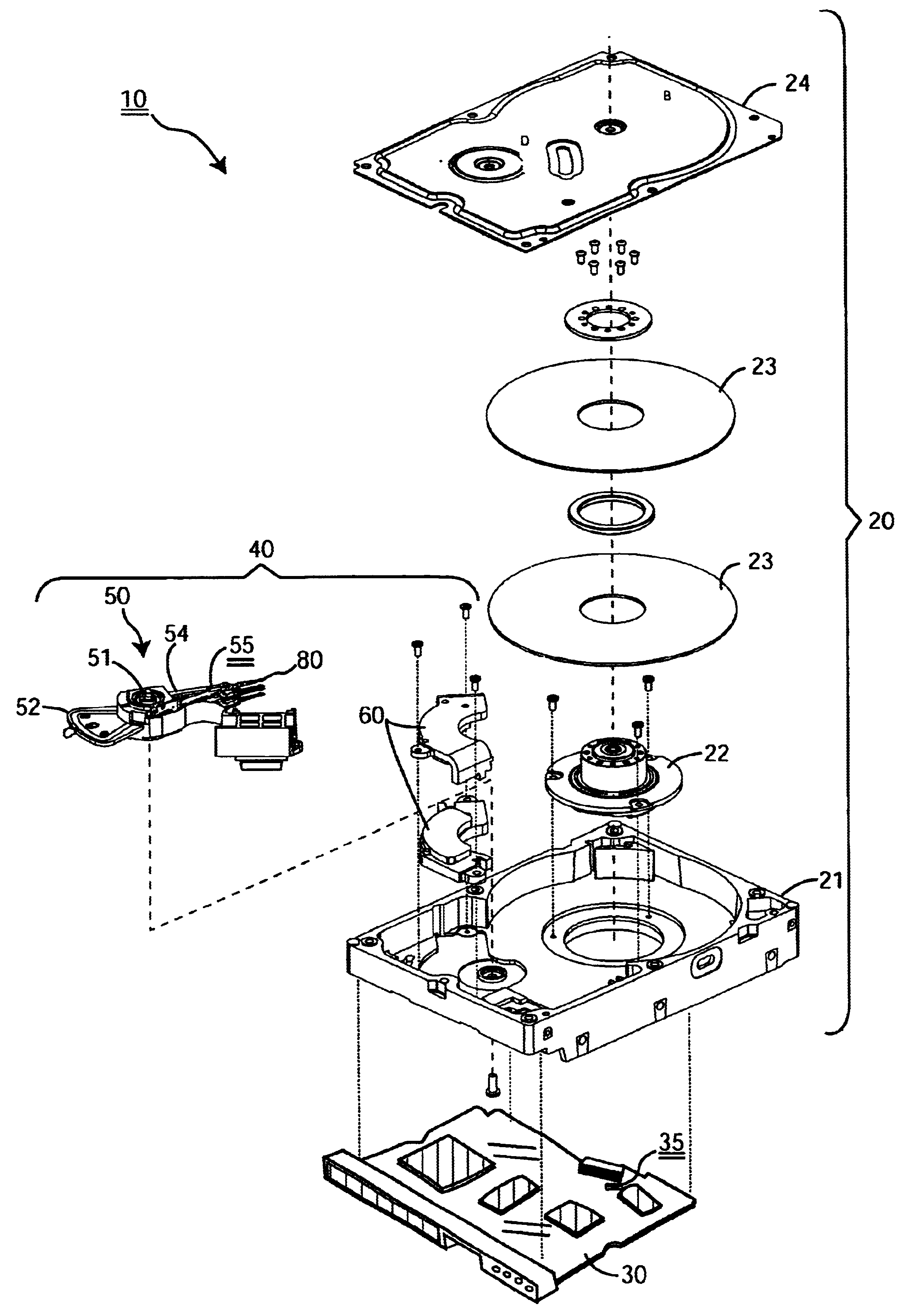
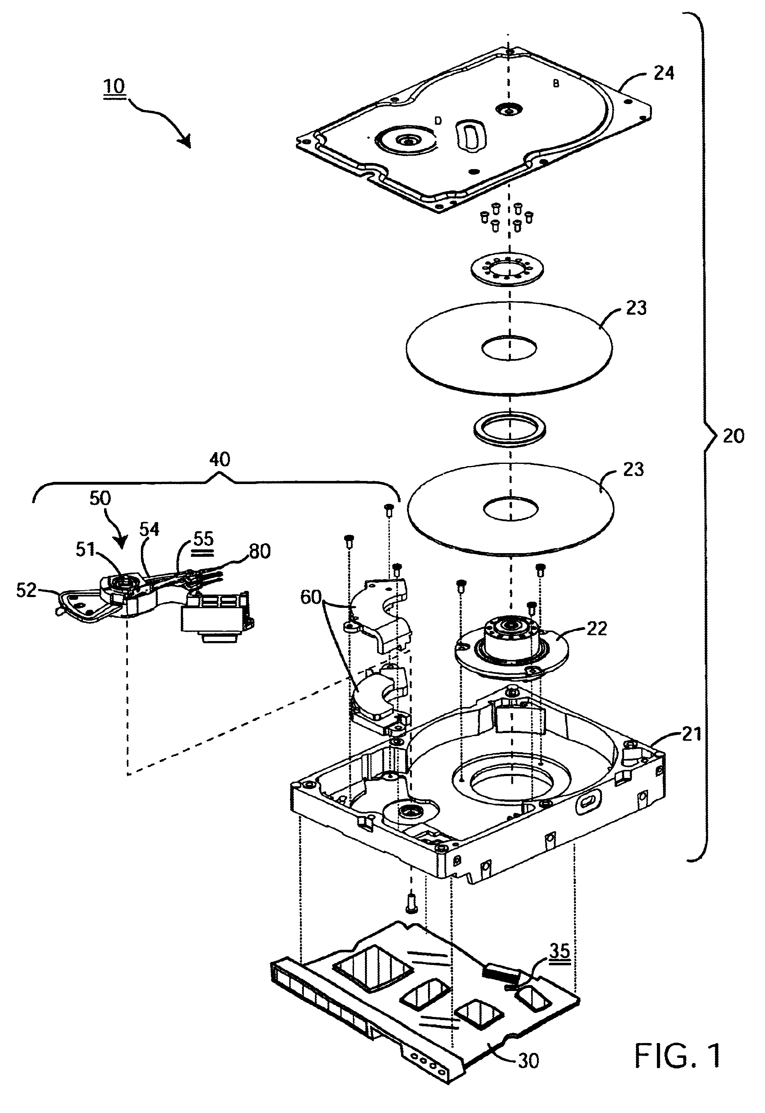
FIG. 1 shows a preferred embodiment of a disk drive 10 according to this invention. As shown, the disk drive 10 comprises a head disk assembly ("HDA") 20 including a base 21, a rotating disk 23, and a rotary actuator 50 that pivots relative to the base 21. In this first embodiment, the disk drive 10 further comprises a first motion sensor 35 rigidly mounted relative to the base 21 for sensing motion of the HDA 20, and a second motion sensor 55 mounted to the rotary actuator 50 for sensing motion of the rotary actuator 50, both with and relative to the motion of the HDA 20.

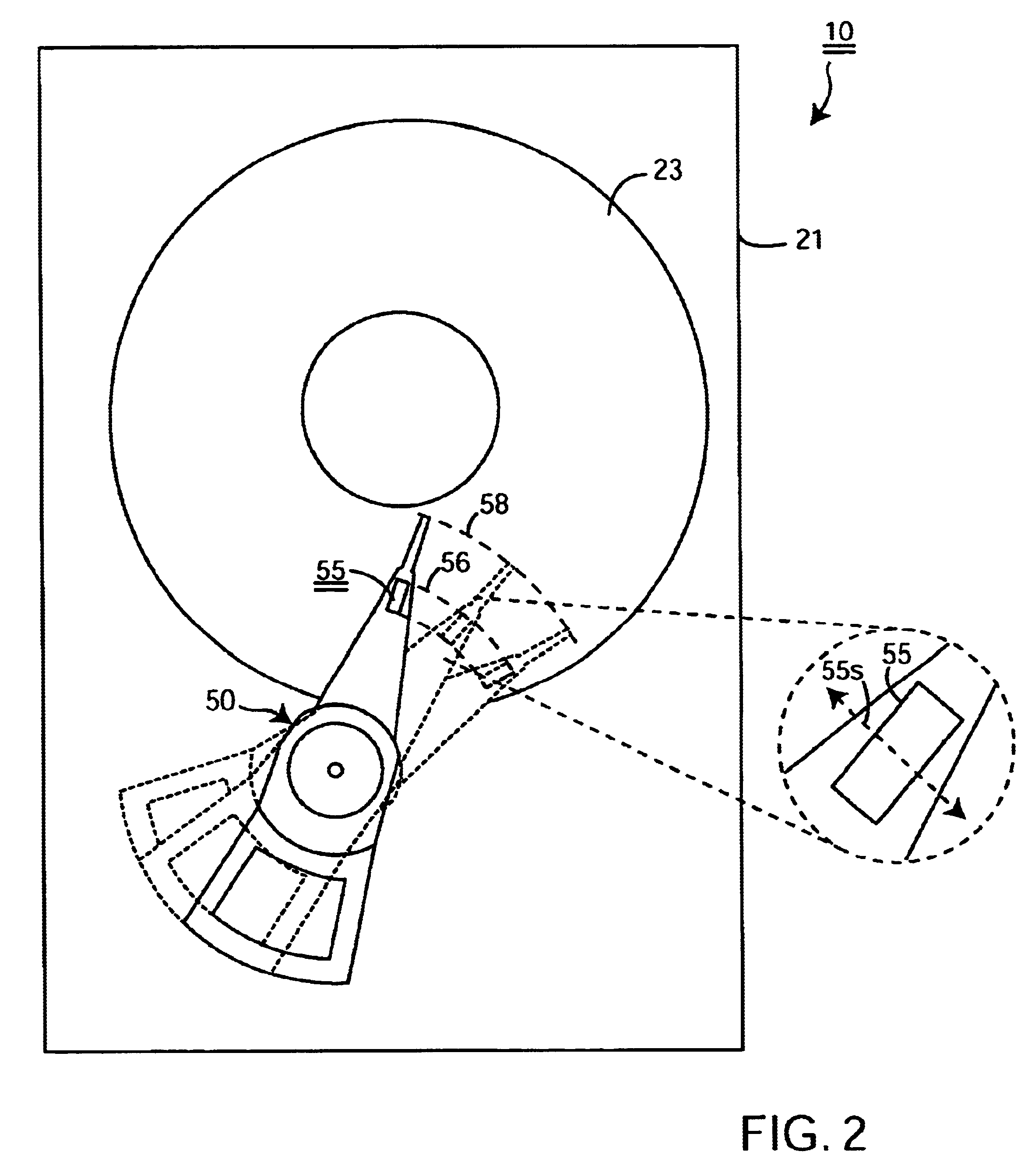
There are preferably two sensors 35, 55, but it is possible to use more than two sensors in a more complicated differential arrangement. The preferred sensors 35, 55 are linear accelerometers with a single sense axis 35s, 55s (see FIG. 2), but multi-axis sensors and other types of motion sensors altogether may also be used in a differential mode in accordance with this invention.

In the preferred embodiment, a PC Bo...


PUM

PropertyMeasurementUnit
diameteraaaaaaaaaa
FREQUENCY RESPONSEaaaaaaaaaa
external forcesaaaaaaaaaa

Abstract

A disk drive that includes a base, a magnetic disk, a rotary actuator that carries a head for reading and writing data from the disk in a track-following mode under the control of a servo control system, and at least two sensors--one fixed sensor rigidly coupled to the overall disk drive and one mobile sensor mounted to the rotating actuator--for differentially detecting accelerations of the rotary actuator relative to the overall disk drive and its disk. The disk drive detects and actively compensates for accelerations imparted to a balanced actuator that has an effective imbalance. The fixed sensor is preferably mounted to a PCBA that is secured to the base. The mobile sensor is preferably mounted to an actuator arm of the rotary actuator, as far outboard as possible, and so as to align with the fixed sensor as the rotary actuator swings through its range of travel. The preferred sensors are linear accelerometers.

Description

FIELD OF THE INVENTIONThe present invention relates generally to magnetic disk drives and, more particularly, to active vibration cancellation within a disk drive using a multitude of accelerometers.BACKGROUND OF THE RELATED ARTMagnetic disk drives generally read and write data on the surface of a rotating magnetic disk with a transducer or "head" that is located at the far end of a moveable actuator. A servo control system uses servo control information recorded amongst the data, or on a separate disk, to controllably move the transducer from track to track ("seeking") and to hold the transducer at a desired position ("track following"). A detailed discussion of servo control systems is unnecessary because such systems are well known as set forth, for example, in patent application Ser. No. 09 / 138,841 that was filed on Aug. 24, 1998, entitled "DISK DRIVE CAPABLE OF AUTONOMOUSLY EVALUATING AND ADAPTING THE FREQUENCY RESPONSE OF ITS SERVO CONTROL SYSTEM," and is commonly owned by the...

Claims


Application Information

Patent Timeline
Patent Type & Authority Patents(United States)
IPC IPC(8): G11B21/02G11B5/55
CPCG11B5/5582G11B21/02
Inventor CODILIAN, RAFFIPATTON, III, CHARLES R.
Owner WESTERN DIGITAL TECH INC
Why Eureka
Try Eureka