Drilling hammer or impact hammer

Inactive Publication Date: 2004-01-13
ROBERT BOSCH GMBH +1
View PDF15 Cites 45 Cited by
  • Summary
  • Abstract
  • Description
  • Claims
  • Application Information

AI Technical Summary

Benefits of technology

The drill hammer or riveter according to the invention having the characteristics of claim 1 has the advantage that the vibration caused by the hammering mechanism can be reduced in a relatively simple way.By the provisions recited in the dependent claims, advantageous refinements of and improvements to the drill hammer or riveter according to the invention are possible.

Problems solved by technology

To the operator of the drill hammer or riveter, these reverse impacts are irritating, so that the attempt is made to avoid or reduce them as much as possible.

Method used


Image

  • Drilling hammer or impact hammer
  • Drilling hammer or impact hammer
  • Drilling hammer or impact hammer

Examples


Embodiment Construction

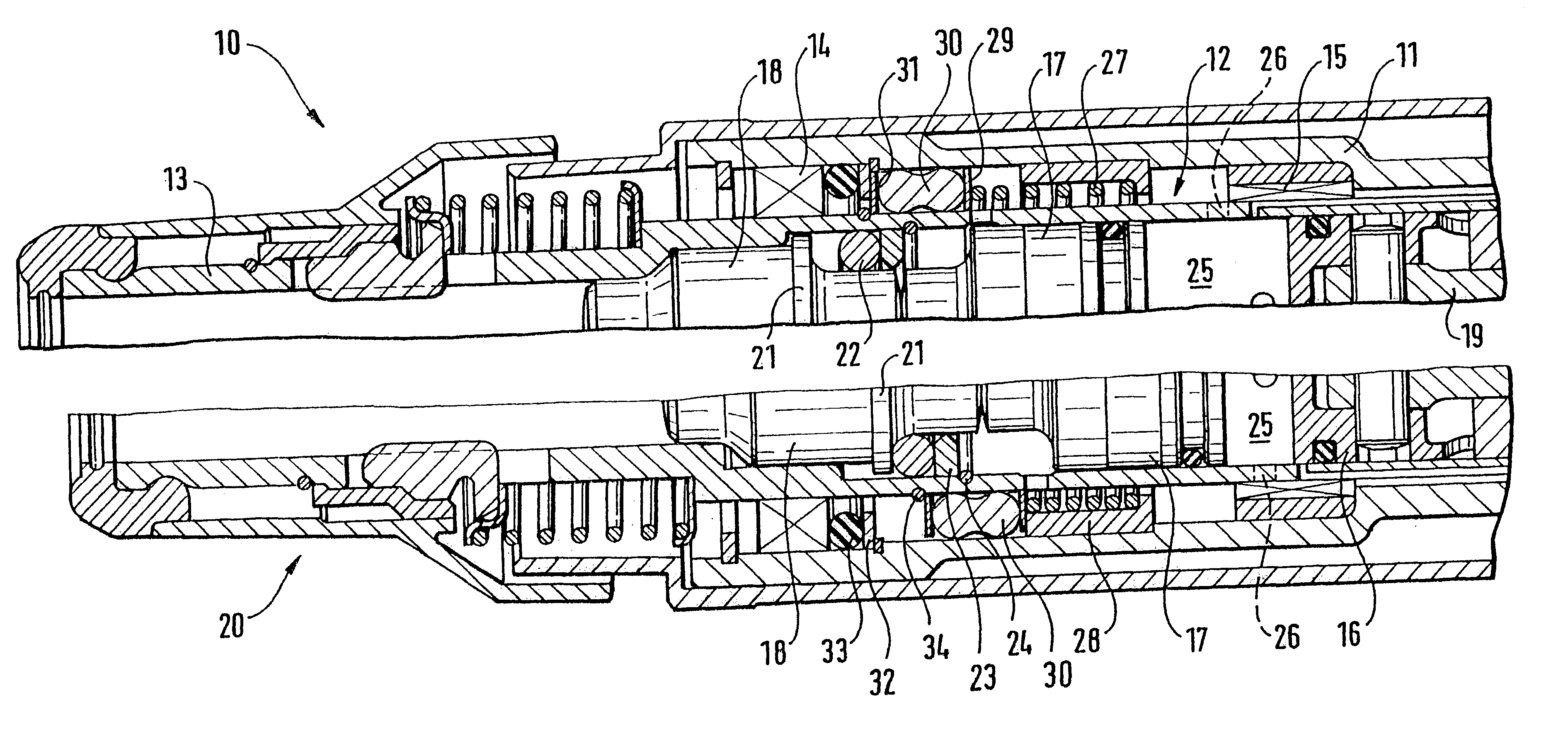
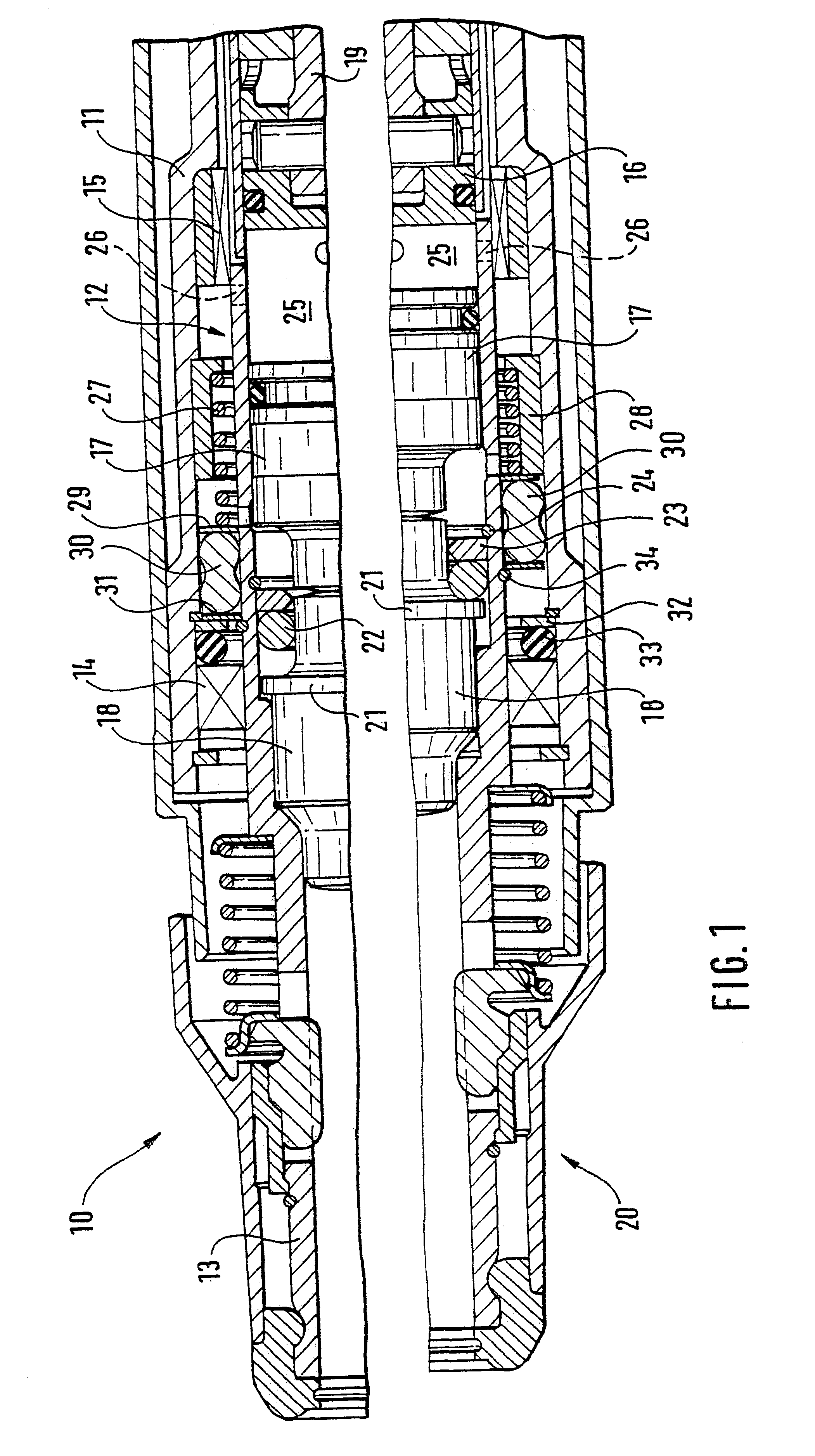
In FIG. 1, reference numeral 10 indicates a drill hammer, which has a housing 11 in which a hammering mechanism 12 is accommodated. Inside the housing 11, a guide tube 13 is rotatable in bearing points 14, 15 and is limitedly displaceable axially. The guide tube, in a known manner, holds a piston 16, a striker 17, and a riveting die 18. The piston 16 can be driven to reciprocate via a connecting rod 19. The guide tube 13, on its end remote from the connecting rod 19, forms a tool holder 20 to receive a tool, not shown in detail.

The riveting die 18 is provided with an encompassing collar 21, by way of which it can be braced to the rear, toward the piston 16, via a damping ring 22 and a stop ring 23 as well as a snap ring 24 on the guide tube 13. Between the piston 16 and the striker 17, an air cushion space 25 is formed, which can be ventilated via radial through bores 26 in the guide tube 13. A restoring spring 27, which is braced toward the housing on a bearing ring 28 solidly conn...


PUM

PropertyMeasurementUnit
restoring forceaaaaaaaaaa
dampingaaaaaaaaaa
axial displacementaaaaaaaaaa

Abstract

A drill hammer or riveter, includes a housing (11), in which a hammering mechanism (12) is accommodated that in an axially displaceably supported guide tube (13) has a reciprocating piston (16) and a striker (17), drivable by the piston (16) via an air cushion; the hammering mechanism (12) can be moved out of an idling position into a hammering position by an axial displacement of the guide tube (13); the guide tube (13) is urged by a restoring spring (27) in the direction of the idling position with a restoring force: and between the guide tube (13) and the housing (11), at least one damping and / or spring member (30, 36, 37) is provided, which in the hammering position of the guide tuber (13) has a spring or damping characteristic between the guide tube (13) and the housing (11) that deviates from the restoring spring (27) in the region of the idling position.

Description

PRIOR ARTThe invention is based on a drill hammer or riveter as generically defined by the preamble to claim 1. From European Patent Disclosure EP-A 429 475, a drill hammer or riveter is known which has a guide tube supported axially displaceably in a housing. An axially reciprocating piston, which is coupled via an air cushion to a striker, is accommodated in the guide tube. A restoring spring urges the guide tube with a restoring force in the direction of a front outset position, in which the air cushion is ventilated via an opening in the guide tube, so that the hammering mechanism of the drill hammer or riveter goes into the idling mode and no further axial impacts are exerted on a tool. If the guide tube is forced axially rearward out of this position by the application of the drill hammer or riveter against a machining point counter to the prestressing force of the restoring spring, then the ventilation opening is closed, and the hammering mechanism enters the hammering positi...

Claims


Application Information

Patent Timeline
Patent Type & Authority Patents(United States)
IPC IPC(8): B25D11/12B25D11/00B23B45/16B25D17/24B25D9/04
CPCB25D11/125
Inventor FRAUHAMMER, KARLMUELLER, FRANKMEIXNER, GERHARDSCHNERRING, HEINZ
Owner ROBERT BOSCH GMBH
Why Eureka
Try Eureka