Multiple shaft diameter flexible coupling system

a flexible coupling and shaft diameter technology, applied in the direction of couplings, rod connections, manufacturing tools, etc., can solve the problems that no one has the purpose or capability of accommodating various shaft diameters

Inactive Publication Date: 2004-01-27
SHINOZUKA KINZOU
View PDF7 Cites 180 Cited by
  • Summary
  • Abstract
  • Description
  • Claims
  • Application Information

AI Technical Summary

Problems solved by technology

And while a variety of hollow, sleeve type, inserts into which shafts are fitted are known which fit the bore of a flexible coupling none have the purpose or capability of accommodating various shaft diameters as none effect a reduction of a flexible shaft coupling bore diameter which could be used without the insert with a larger diameter shaft.

Method used


Image

  • Multiple shaft diameter flexible coupling system
  • Multiple shaft diameter flexible coupling system
  • Multiple shaft diameter flexible coupling system

Examples


Embodiment Construction

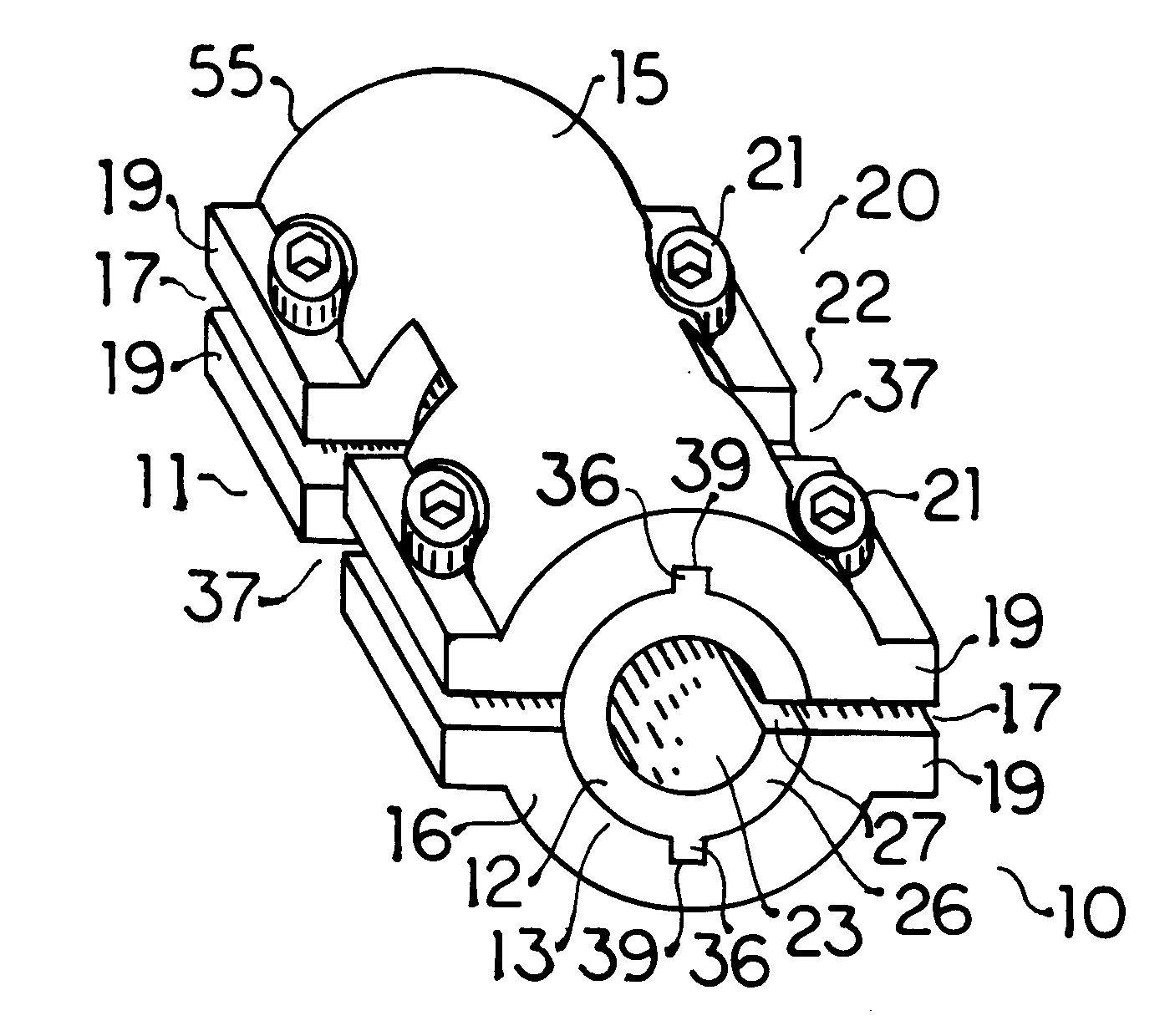
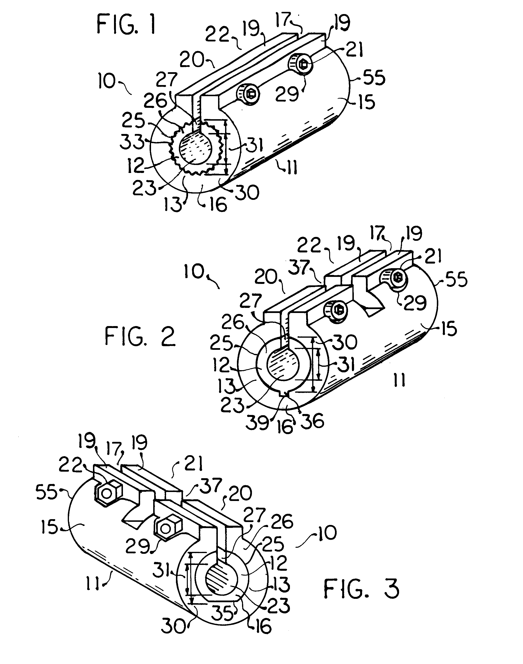
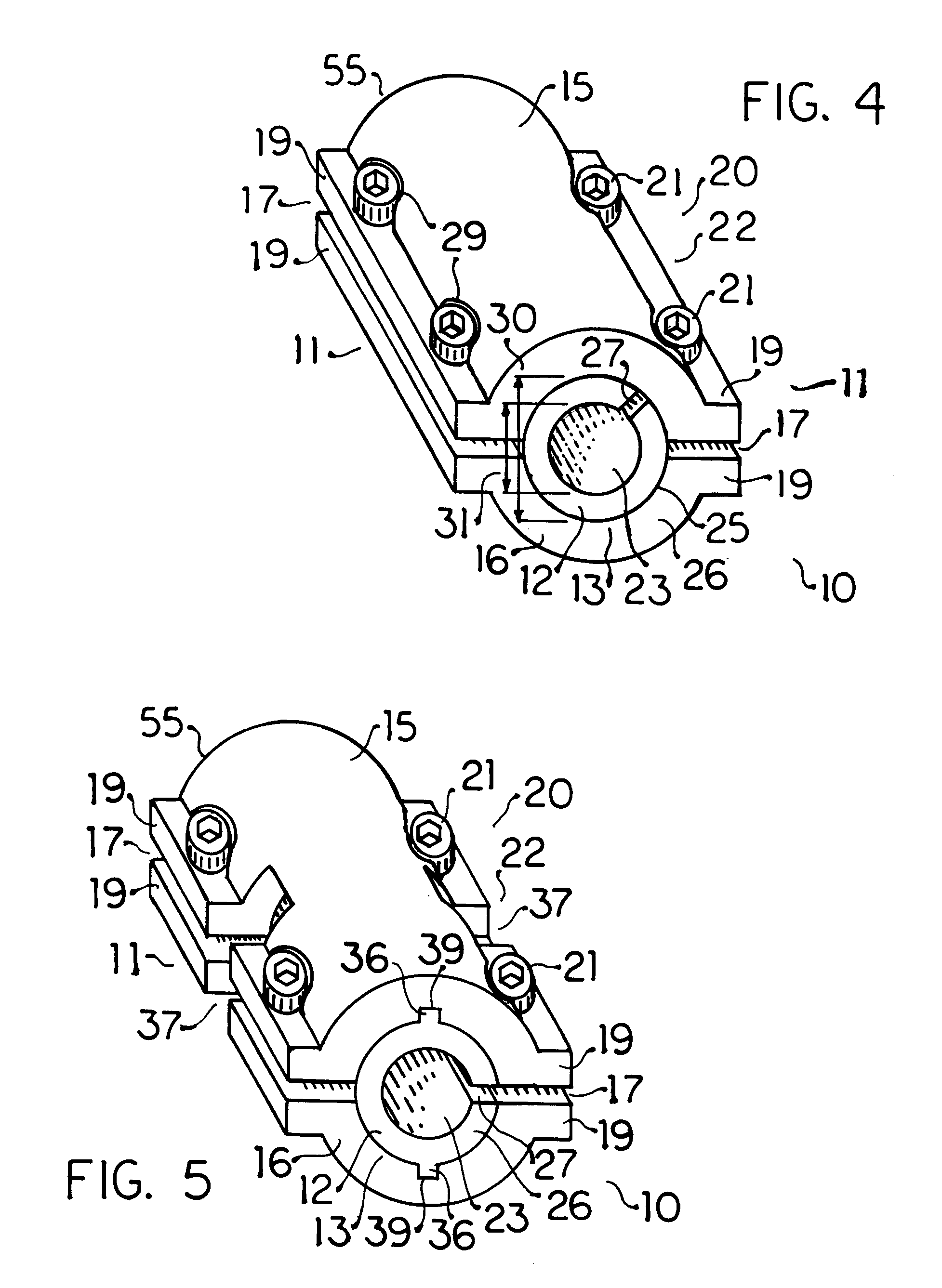
A multiple diameter coupling system 10 in accordance with the principles relating to the present invention, as depicted in FIG. 1, includes a rotary shaft coupling 11 with two opposed bores 13 each open to one end 55 of the coupling 11 and a radially compressible sleeve insert 12 disposed in at least one said bore 13 effectively reducing the diameter of the same. The coupling 11 depicted in FIG. 1 possesses a simple straight substantially cylindrical configuration of substantially uniform, solid, wall 16 thickness except for one longitudinal slot 17 interrupting the circumferential extension of the wall 16 and the opposed pair of longitudinal bosses 19 extending radially outward from the otherwise cylindrical wall 16 along either side of this single longitudinal slot 17 which facilitate partial closing of the same with the use of two threaded fasteners 20 each located in association with, i.e. operably upon, one bore 13 and preferably comprised, as shown therein, of one bolt 21 trav...


PUM


Abstract

Compression exerted by a clamp collar integral to a molded plastic flexible shaft coupling accommodating angular shaft misalignment upon the circumferential outward surface of a radially compressible molded sleeve insert located in a shaft bore of the flexible coupling facilitates engagement of a reduced diameter shaft located within the sleeve insert. Use of a sleeve insert having a different internal diameter similarly accommodates flexible coupling to another diameter shaft. Utilization of sleeve inserts selected from a plurality of different reduced internal diameters and exterior diameters sized to fit either shaft bore enables flexible coupling of both multiple matched shaft diameters and an exponential number of differing opposed shaft diameter combinations within a range limited by the flexible coupling shaft bores. Radial compressibility of the sleeve insert is facilitated by the utilization of resilient material, interruption of the circumferential extension by a longitudinal slot, or both. Utilization of congruent longitudinally uniform, radially non-uniform, flexible coupling shaft bore and insert sleeve outward surfaces provides additional torque transmission capacity.

Description

1. Field of the InventionThe field of the present invention relates:generally to flexible couplings for rotary shafts transmitting torque via a flexible element;more particularly to flexible couplings for rotary shafts transmitting torque via a flexible element facilitating angular misalignment; andmost specifically to the use of sleeve inserts in flexible coupling of rotary shafts with torque transmission via a flexible element that facilitates angular misalignment.2. General BackgroundIt is considered that the basic, fundamental, purpose of a flexible shaft coupling is the transmission of torque between drive and driven shafts possessing a small degree of angular misalignment between substantially aligned rotational axes. In this context it is next considered that flexible shaft couplings are used in a huge range of applications which can perhaps best be demarcated by one simple opposition between larger, dedicated, applications and smaller, variable, applications. The coupling of...

Claims


Application Information

Patent Timeline
Patent Type & Authority Patents(United States)
IPC IPC(8): F16B2/02F16B2/06F16B2/22F16D3/50F16D3/72F16B2/20
CPCF16B2/065F16B2/22F16D3/72Y10T403/453Y10T403/452Y10T403/69Y10T403/535F16D1/0864
Inventor SHINOZUKA, KINZOU
Owner SHINOZUKA KINZOU
Why Eureka
Try Eureka