Rotational angle sensor assembly

a sensor and rotational angle technology, applied in the direction of mechanical measurement arrangement, instruments, using mechanical means, etc., can solve the problems of increasing the cost of manufacture, unable to allow the rotary shaft to be loaded with a relatively high load, and prone to large errors in the detected rotation angl

Inactive Publication Date: 2004-02-10
NTN CORP
View PDF12 Cites 21 Cited by
  • Summary
  • Abstract
  • Description
  • Claims
  • Application Information

AI Technical Summary

Problems solved by technology

The standard rotational angle detecting potentiometer hitherto used makes use of an oil retaining metal or a relatively small rolling bearing in order to permit the rotary shaft to be rotatably supported relative to a housing and is incapable of allowing the rotary shaft to be loaded with a relatively high load.
When a relatively high load is imposed on the rotary shaft in one or both of axial and radial directions thereof, a relatively large error tends to occur in the detected angle of rotation.
Also, in order for the bearings 53 to be set in position under a pre-loaded condition, the annular spacer 59 and / or the flange 52b between the two bearings 53 must have a thickness carefully designed to be consistent with the size of the bearings and do thus require a precise machining accuracy, resulting in increase of the cost of manufacture.
Although the rotational angle detecting means in the form of a potentiometer is simple in structure, any possible change in a biasing force used to urge the slide brush so as to keep the slide brush in sliding contact with the resistor and / or the electroconductive element would eventually result in an error in measurement of the angle of rotation of the rotary shaft.

Method used


Image

  • Rotational angle sensor assembly
  • Rotational angle sensor assembly
  • Rotational angle sensor assembly

Examples


Embodiment Construction

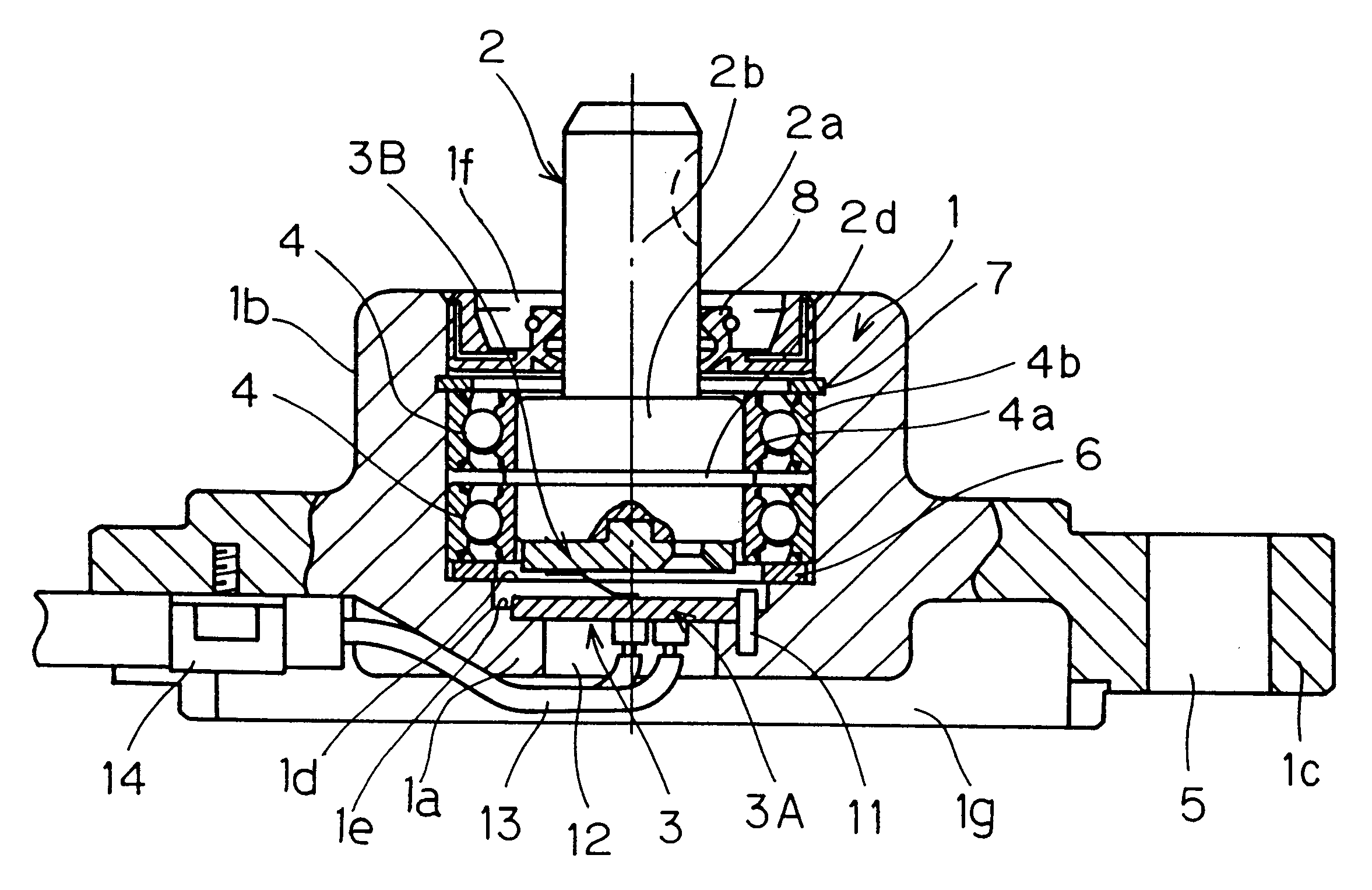
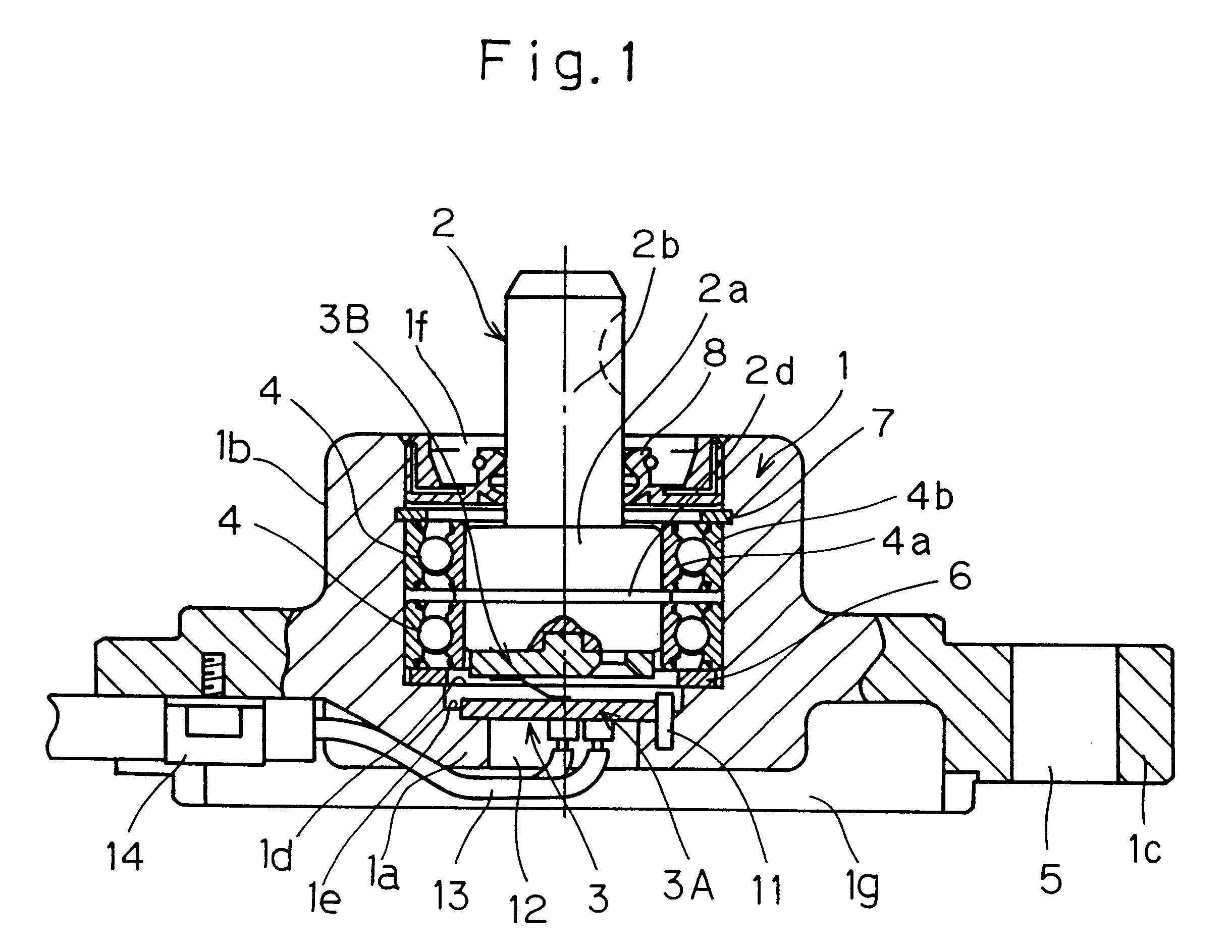
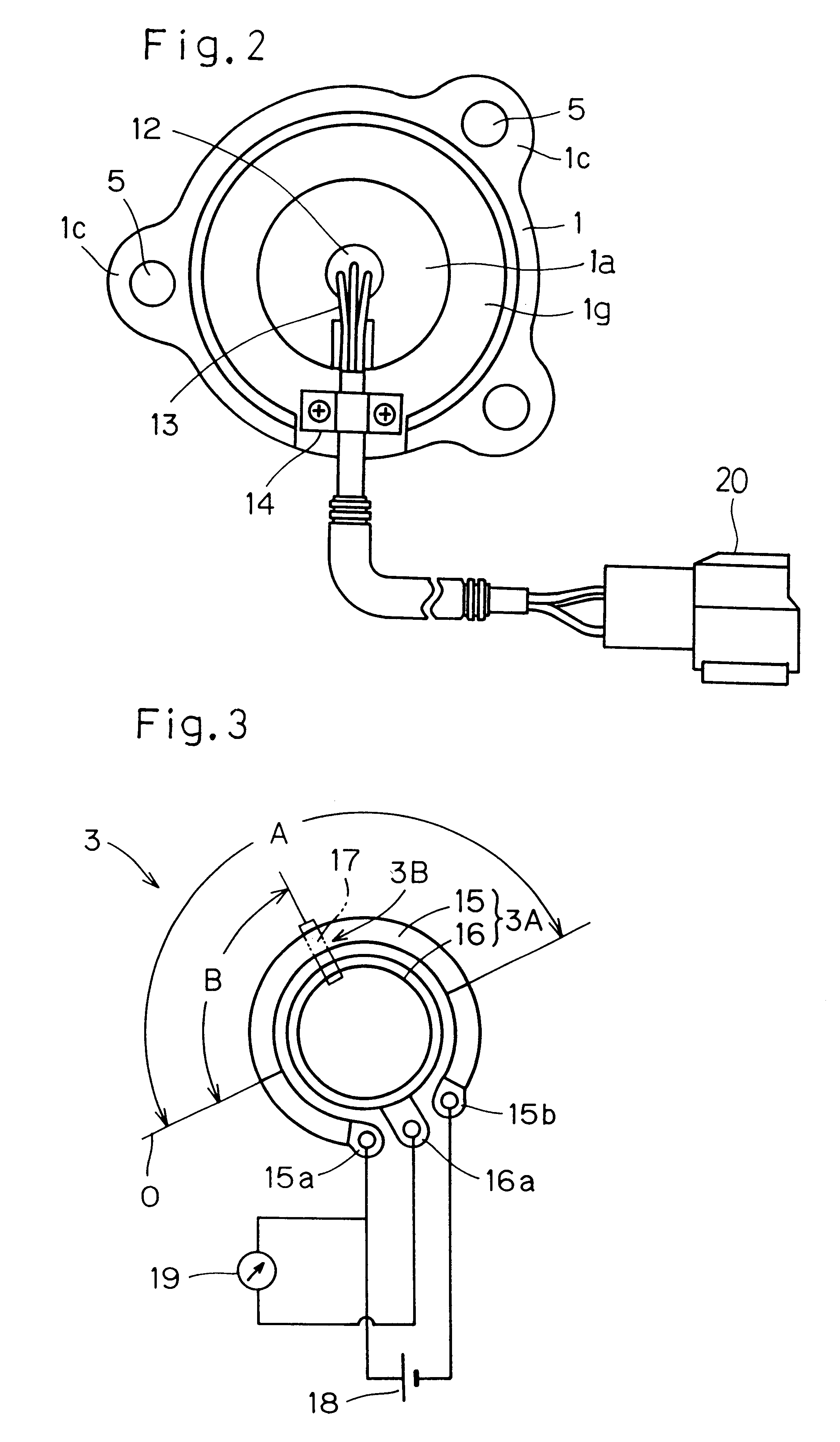
A rotational angle sensor assembly according to a preferred embodiment of the present invention will now be described with reference to FIGS. 1 to 3. The rotational angle sensor assembly includes, as shown in FIG. 1, a housing 1 of a cup-like configuration having a bottom wall 1a and a tubular side wall 1b and opening upwardly at 1f. The illustrated rotational angle sensor assembly also includes a rotational angle detecting means 3 made up of a first rotational angle detector 3A, disposed at the bottom of a cylindrical hollow of the housing 1, and a second rotational angle detector 3B mounted on one end of a rotary shaft 2 within the housing 1. The rotary shaft 2 is rotatably supported by upper (first) and lower (second) bearings 4 and 4 that are press-fitted into the cylindrical hollow of the housing 1 with a portion 2b on the side of the opposite end thereof protruding outwardly from the opening 1f of the housing 1. As shown in FIG. 2, the housing 1 has a plurality of mounting ton...


PUM


Abstract

In order to minimize change in base position from which an output representative of the angle of rotation of a rotary shaft (2) relative to a housing (1) is based, to reduce the number of component parts used, to enable a load acting on the rotary shaft (2) to be supported and to enable a rotational angle sensor assembly to be assembled with a simplified machining operation, the rotational angle sensor assembly includes a rotational angle detecting means (3) for detecting the angle of rotation between mutually opposed first and second rotational angle detectors (3A) and (3B). A housing (1) is of a cup-shaped configuration having a hollow defined therein, with the first rotational angle detector (3A) disposed at the bottom of the housing hollow. The second rotational angle detector (3B) is mounted on one end of the rotary shaft (2) that is rotatably supported by rolling bearings (4). The bearings (4) are pre-loaded at a predetermined pressure by a spring member (6). A portion of the rotary shaft (2) remote from the first rotational angle detector (3A) extends outwardly from an opening (1f) of the housing (1).

Description

1. Field of the InventionThe present invention generally relates to a sensor assembly for detecting the angle of rotation of elements relative to each other and, more particularly, to the rotational angle sensor assembly for use in construction machinery and industrial machinery for detecting the angle of rotation of a rotating element such as, for example, a rotary shaft or an oscillating shaft while the latter is operated under a loaded condition.2. Description of the Prior ArtAs an instrument for measuring the angle of rotation of a rotary shaft or an oscillating shaft, a rotational angle detecting potentiometer has long been used. The rotational angle detecting potentiometer includes an electroconductive brush movable together with, for example, a rotary shaft and an electric resistor held in sliding contact with the brush. The potentiometers provides a voltage signal represented by the resistance of the resistor which varies depending on the position of the electroconductive br...

Claims


Application Information

Patent Timeline
Patent Type & Authority Patents(United States)
IPC IPC(8): G01D5/12G01D5/165G01B7/30
CPCG01D5/165
Inventor ITOMI, SHOJI
Owner NTN CORP
Why Eureka
Try Eureka