Corrugated fin heat exchanger and method of manufacture

a heat exchanger and corrugated fin technology, applied in the field of corrugated fin heat exchangers and methods of manufacture, can solve the problems of increasing the cost of manufacture, limited contact area between the tube sections and the corrugated sheet,

Inactive Publication Date: 2004-02-10
AAVID THERMALLOY LLV
View PDF25 Cites 31 Cited by
  • Summary
  • Abstract
  • Description
  • Claims
  • Application Information

AI Technical Summary

Benefits of technology

According to the invention, this object is achieved by forming each first peak with at least one depression, the depressions in respective peaks being aligned to form at least one tube-receiving channel extending transversely to the longitudinal direction of the peaks and troughs. The channels are typically straight (rectilinear), but may be curved or otherwise routed to accommodate tubing which is formed to maximize heat transfer in a desired area of the corrugated sheet, as may be dictated by the location of components to be cooled. Each depression has a contact surface formed in the first side and extending laterally over each adjacent first trough, the contact surface being profiled to conform closely to a tube section received thereagainst. The contact surface profile is circular when standard round tubing is used, but may be formed to accommodate tubing having other shapes. For example, tubing having an oval cross-section may be used to minimize resistance to airflow by the parts of the tubing sections which stand proud of the peaks. The tube sections can thus be received in the tube-receiving channels with an area of thermal contact which is very large in comparison with the prior art, even before solder is applied. The use of solder or epoxy may therefore be minimized, which reduces the cost of manufacture. The contact surfaces also provide for easy deposition of solder for a reflow process.
In order to stabilize the corrugated metal sheet while the tube-receiving channels are being formed, a second fixture is used. The second fixture includes a second base and a plurality of second ribs fixed to the second base, the second ribs and the second base being interrupted to form at least one window extending through the second fixture. The second fixture is placed onto the first fixture after the corrugated sheet is emplaced on the first fixture, and before forming the first peaks downward into the notches to form the depressions, the second ribs being received in the first troughs and the windows being aligned with the forming channels. The first peaks can then be deformed downward to form the tube-receiving channels by using at least one mandrel received through the windows in the second fixture. The second fixture stabilizes the corrugations against deformation except in the areas immediately adjacent to the notches in the first ribs, whereby peaks of the corrugated sheet are formed downward and laterally into the windows, so that the resulting contact surfaces extend laterally over the adjacent first troughs.

Problems solved by technology

The prior art suffers from the disadvantage that the contact area between the tube sections and the corrugated sheet is very limited.
This adds to the cost of manufacture.

Method used


Image

  • Corrugated fin heat exchanger and method of manufacture
  • Corrugated fin heat exchanger and method of manufacture
  • Corrugated fin heat exchanger and method of manufacture

Examples


first embodiment

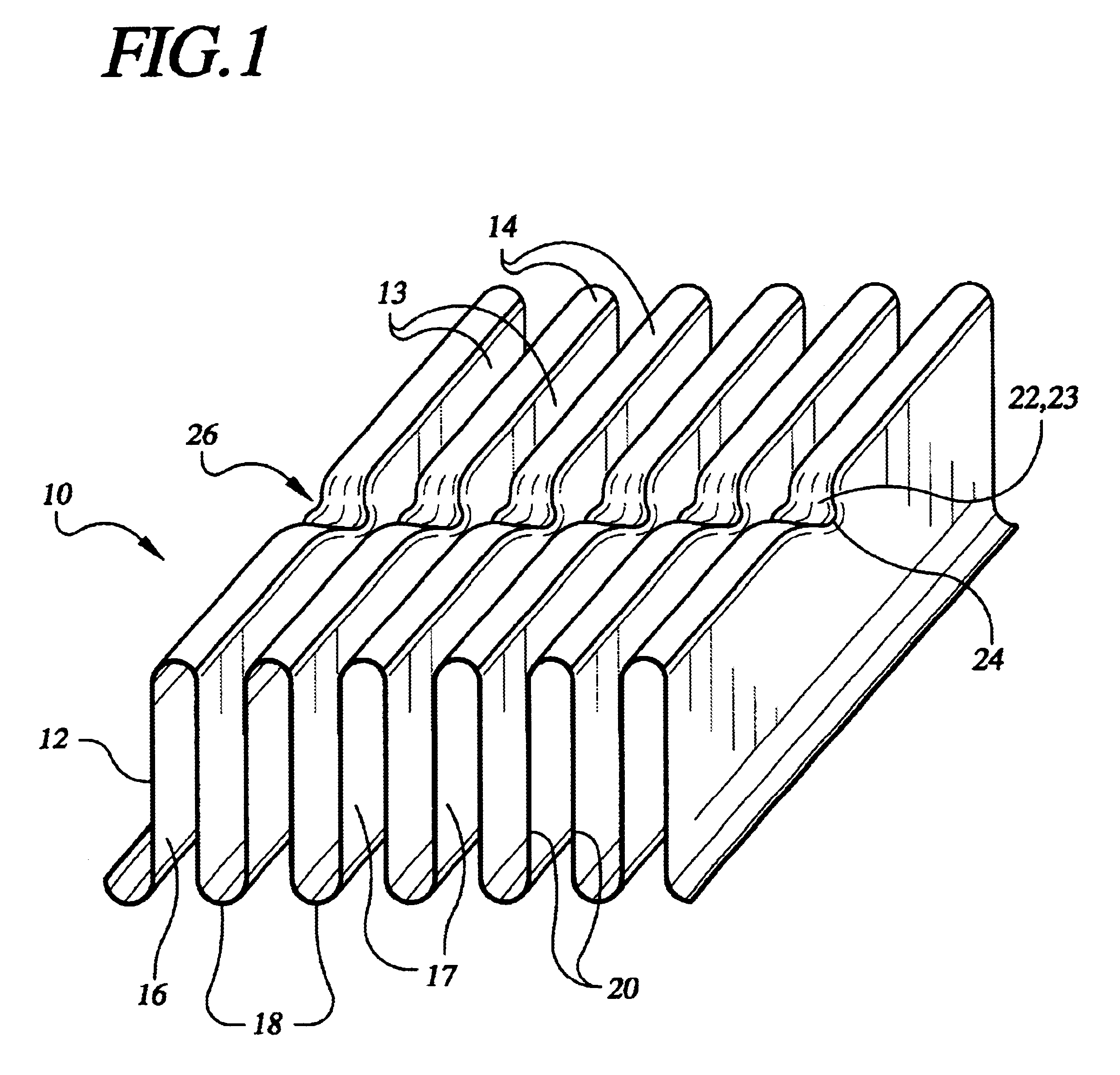
FIG. 2 shows the heat exchanger according to the invention, wherein the tube sections 28 are connected to coolant headers 29 so that the coolant flows through the sections in parallel.

second embodiment

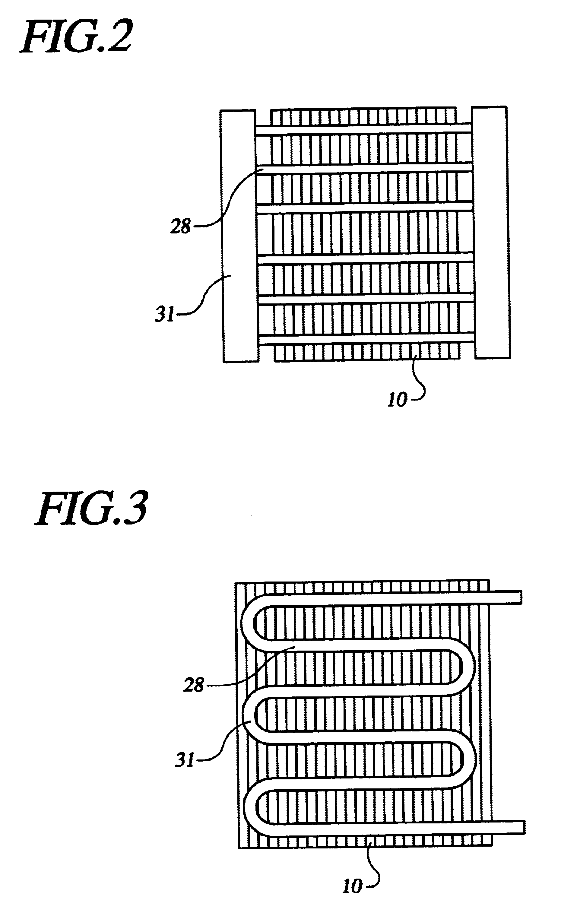
FIG. 3 shows the heat exchanger according to the invention, wherein the tube sections 28 are connected in series by U-sections 31 to form a continuous serpentine tube.

FIG. 4 shows the first fixture 40, the second fixture 50, and the mandrels 60 which are used to form the channels 26 in the corrugated sheet 10. The first fixture 40 includes a base 42 to which first ribs 44 are fixed in parallel. The ribs may be manufactured separately and welded to the base, but the fixtures are preferably machined as integral units, preferably by EDM (electrical discharge milling) methods. Each first rib 44 has an edge 45 remote from the base, each edge being formed with notches 46, each notch 46 being aligned with notches in other first ribs to define forming channels 48. The notches 46 have an arcuate profile which substantially matches the profile of the depressions 22 to be formed in the corrugated sheet. The corners between the top edges 45 and the notches 46 are rounded to prevent damage to th...


PUM

PropertyMeasurementUnit
thickaaaaaaaaaa
heataaaaaaaaaa
contact areaaaaaaaaaaa

Abstract

A heat exchanger includes a corrugated metal sheet comprising a first side having a plurality of first troughs alternating with a plurality of first peaks, and a second side having a plurality of second troughs alternating with a plurality of second peaks, each trough being formed by a pair of walls, each wall separating the first side from the second side and extending from a first peak to a second peak, the troughs and peaks extending in parallel and defining a longitudinal direction. Each first peak is formed with at least one depression, the depressions in respective peaks being aligned to form at least one tube-receiving channel extending transversely to the longitudinal direction. Each depression has a contact surface formed in the first side and extending laterally over each adjacent first trough. A tube section is received in each tube-receiving channel in substantially conforming contact with the contact surfaces. The heat exchanger is manufactured using first and second fixtures having first and second sets of parallel ribs which are received in respective second and first troughs of the corrugated sheet. The first peaks are formed downward using a mandrel received through windows interrupting the second ribs, the depressions being formed in corresponding notches in the first ribs.

Description

1. Field of the InventionThe invention relates to a heat exchanger of the type comprising a corrugated metal sheet in close contact with tube sections. The invention further relates to a method and an apparatus for manufacturing such a heat exchanger.2. Description of the Related ArtA corrugated sheet includes a first side having a plurality of first troughs alternating with a plurality of first peaks, and a second side having a plurality of second troughs alternating with a plurality of second peaks. Each trough is formed by a pair of walls, each wall separating the first side from the second side and extending from a first peak to a second peak, the troughs and peaks extending in parallel and defining a longitudinal direction.Heat exchangers utilizing a corrugated metal sheet in close contact with cooling tube sections are well known. The cooling tube sections are typically soldered to the peaks of the corrugated sheet transversely to the longitudinal direction, as disclosed by U....

Claims


Application Information

Patent Timeline
Patent Type & Authority Patents(United States)
IPC IPC(8): F28F1/12
CPCF28F1/126F28F1/22Y10T29/4938
Inventor LAVOCHKIN, RONALD B.WHITNEY, BRADLEY R.
Owner AAVID THERMALLOY LLV
Why Eureka
Try Eureka