Electric connector having conductive inner and outer shells securely fastened to each other

a technology of electrical connectors and inner shells, applied in the direction of coupling protective earth/shielding arrangements, coupling device connections, coupling bases/cases, etc., can solve the problems of prying forces affecting the coupling parts of the outer wall shell and the inner wall shell

Inactive Publication Date: 2004-02-10
JST MFG CO LTD
View PDF5 Cites 19 Cited by
  • Summary
  • Abstract
  • Description
  • Claims
  • Application Information

AI Technical Summary

Benefits of technology

In this electric connector, as the inner wall shell is fastened to the outer wall shell at both ends, in the width direction, of the intermediate part thereof, a coupling strength between the outer wall shell and the inner wall shell can be secured. In this case, as two top ends of a thrust-in part being formed on at least one end, in the width direction, of the intermediate part of the inner wall shell are fastened into the two slits of the outer wall shell, the area of the fastening parts is greater than that of the conventional connectors, and in turn the coupling strength between the outer wall shell and the inner wall shell is improved proportionately. As a result, the anti-prying strength against prying forces that are exerted by the counterpart connectors is enhanced, and the electric connector is reliably prevented from being damaged. Moreover, when the outer wall shell is fitted onto the body, the coupling strength between the outer wall shell and the body will be enhanced much more, and the anti-prying strength against the prying forces exerted by the counterpart connectors will be increased much more and the electric connector will be more reliably prevented from being damaged.

Problems solved by technology

When counterpart connectors are connected to this electric connector and the electric connector is subjected to prying forces exerted by the counterpart connectors, the coupling parts of the outer wall shell and the inner wall shell may be damaged by these prying forces.

Method used


Image

  • Electric connector having conductive inner and outer shells securely fastened to each other
  • Electric connector having conductive inner and outer shells securely fastened to each other
  • Electric connector having conductive inner and outer shells securely fastened to each other

Examples


Embodiment Construction

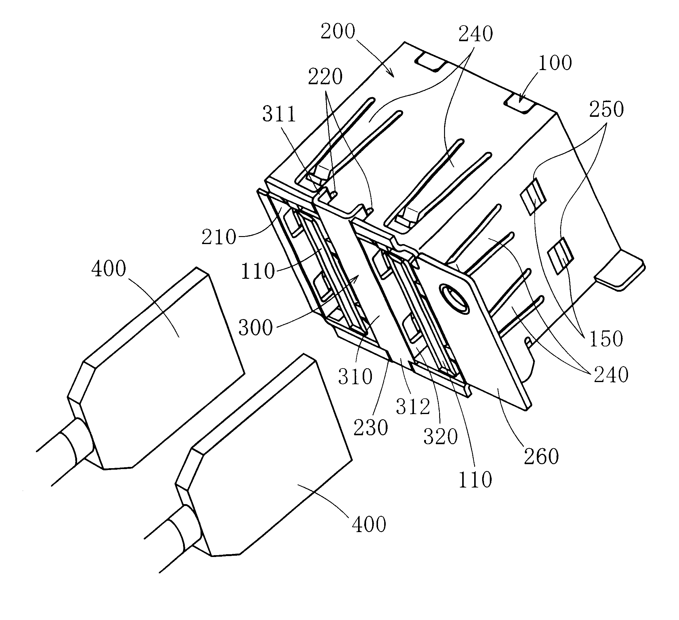
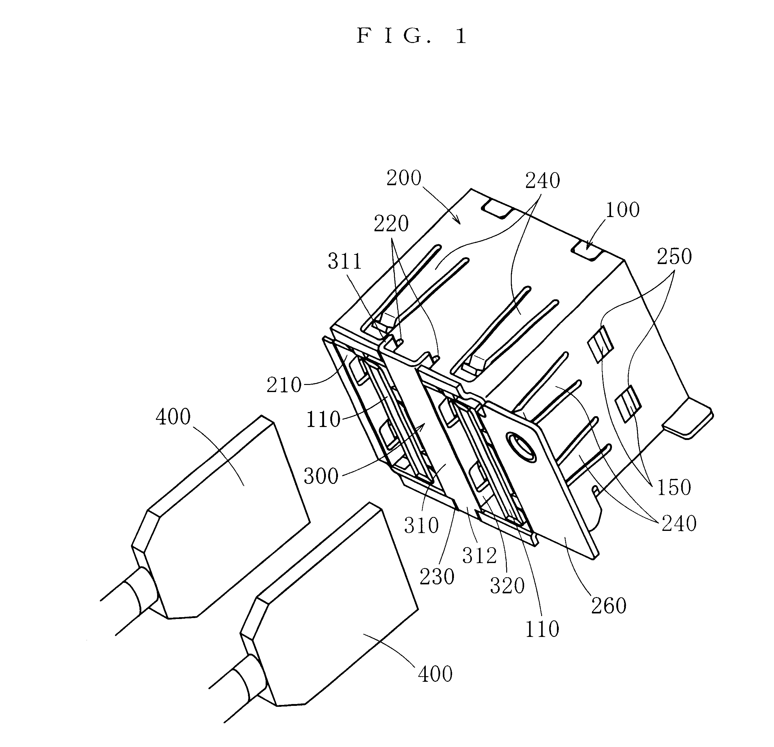
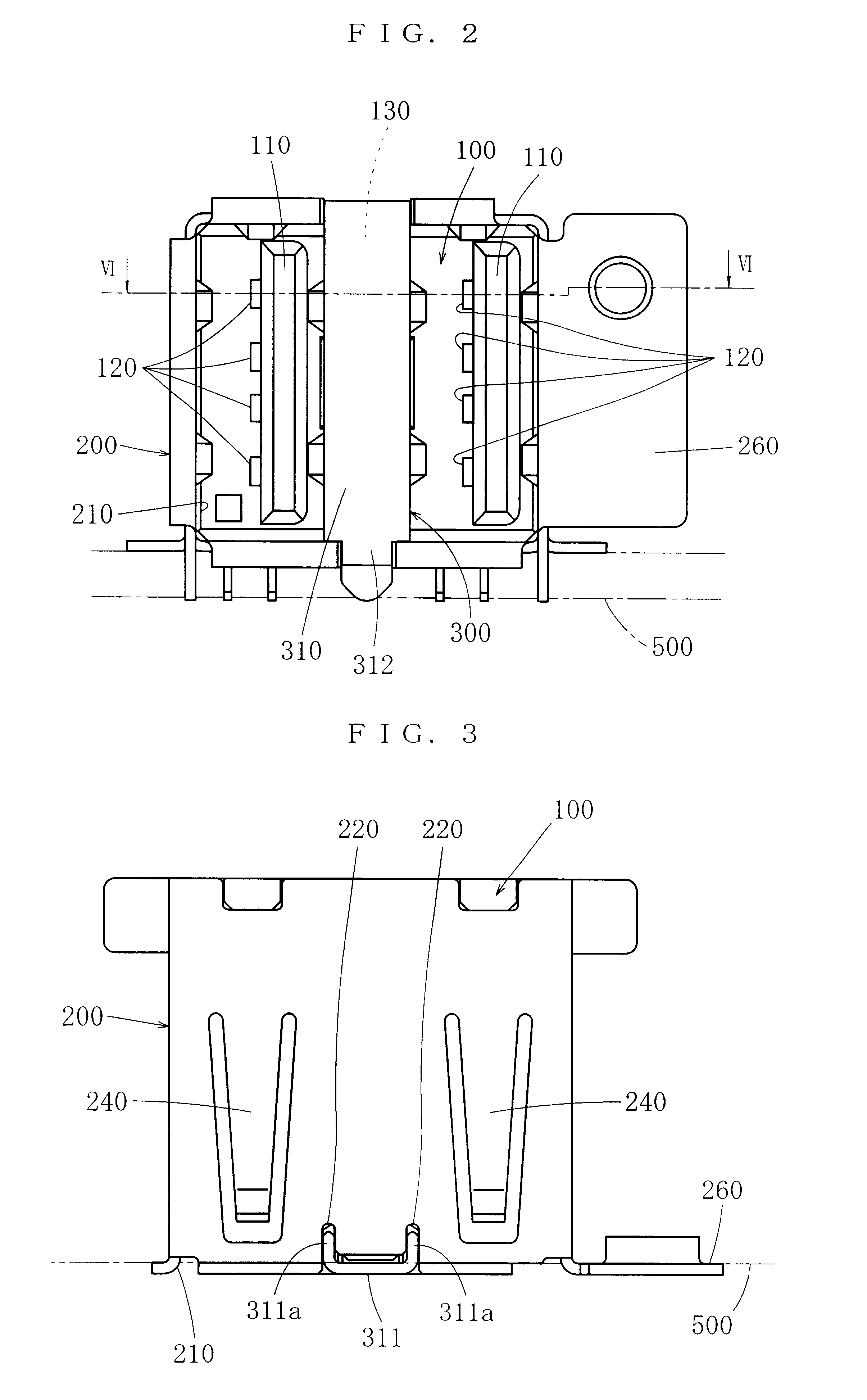
In the following, some embodiments of the present invention will be described. FIG. 1 through FIG. 8 show the first embodiment of the electric connector. This electric connector is of the two pole type, namely, an electric connector to which two counterpart connectors can be connected. The number of poles of the present invention, however, is not limited by this embodiment, and the present invention is applicable to any electric connectors having two or more poles, namely, electric connectors of the multiple stage type. This electric connector is used, for example, by mounting it on a printed circuit board, but the mode of its use is not limited to that.

This electric connector comprises a body 100 made of an insulator, an outer wall shell 200 for shielding, which is provided on the body 100 and is made of a conductor, and an inner wall shell 300 for shielding, which is provided on the body and is made of a conductor.

On the front side of the body 100, connection parts 110, to which c...


PUM


Abstract

An electric connector includes an insulating body, wherein connection parts to be connected with counterpart connectors are arranged in the height direction, a conductive outer wall shell put on the body and having an opening on the front side, and a conductive inner wall shell for partitioning the connection parts. Both the ends, in the width direction, of the intermediate part of the inner wall shell are extended to fasten to the outer wall shell, and at least one end is formed into an approximately-U-shaped thrust-in part rising from the front side toward the rear side when seen in the width direction, and two top ends on the rear side of the thrust-in part are fastened into two slits formed in the outer wall shell. Thereby, the coupling strength between the outer and inner wall shells and the anti-prying strength against prying forces exerted by counterpart connectors are enhanced significantly, and the electric connector is reliably prevented from being damaged.

Description

1. Field of the InventionThe present invention belongs to a field of electric connectors which are covered by shells for shielding and wherein connection parts for connecting with counterpart connectors are provided in multiple stages, and in particular, relates to the coupling structure of the shells for shielding.2. Related ArtAs for electric connectors of this kind, for example, Japanese Patent unexamined publication gazette 2000-260515 disclosed in the past an electric connector comprising a body made of an insulator, and an outer wall shell and an inner wall shell both being made of a conductor. In this body, on the front side thereof, connection parts having terminals and being to be connected with counterpart connectors are arranged in stages in the height direction. The outer wall shell is put on the body to shield the connection parts and is provided with an opening on the front side. The inner wall shell is provided to partition the connection parts and comprises an interm...

Claims


Application Information

Patent Timeline
Patent Type & Authority Patents(United States)
IPC IPC(8): H01R13/658H01R13/00H01R13/46H01R13/648H01R13/6581
CPCH01R12/707H01R13/65802Y10S439/939H01R12/725H01R13/6582H01R13/659
Inventor MORIWAKE, RYOTSUTSUI, TAKASHI
Owner JST MFG CO LTD
Why Eureka
Try Eureka