Engine control for watercraft

a technology for watercraft and control systems, applied in the direction of electric control, special purpose vessels, vessel construction, etc., can solve the problem of limited maximum output of engines

Inactive Publication Date: 2004-02-24
YAMAHA MOTOR CO LTD
View PDF10 Cites 46 Cited by
  • Summary
  • Abstract
  • Description
  • Claims
  • Application Information

AI Technical Summary

Problems solved by technology

When the output control is switched to the air-restricting state, the maximum output of the engine is limited.

Method used


Image

  • Engine control for watercraft
  • Engine control for watercraft
  • Engine control for watercraft

Examples


Embodiment Construction

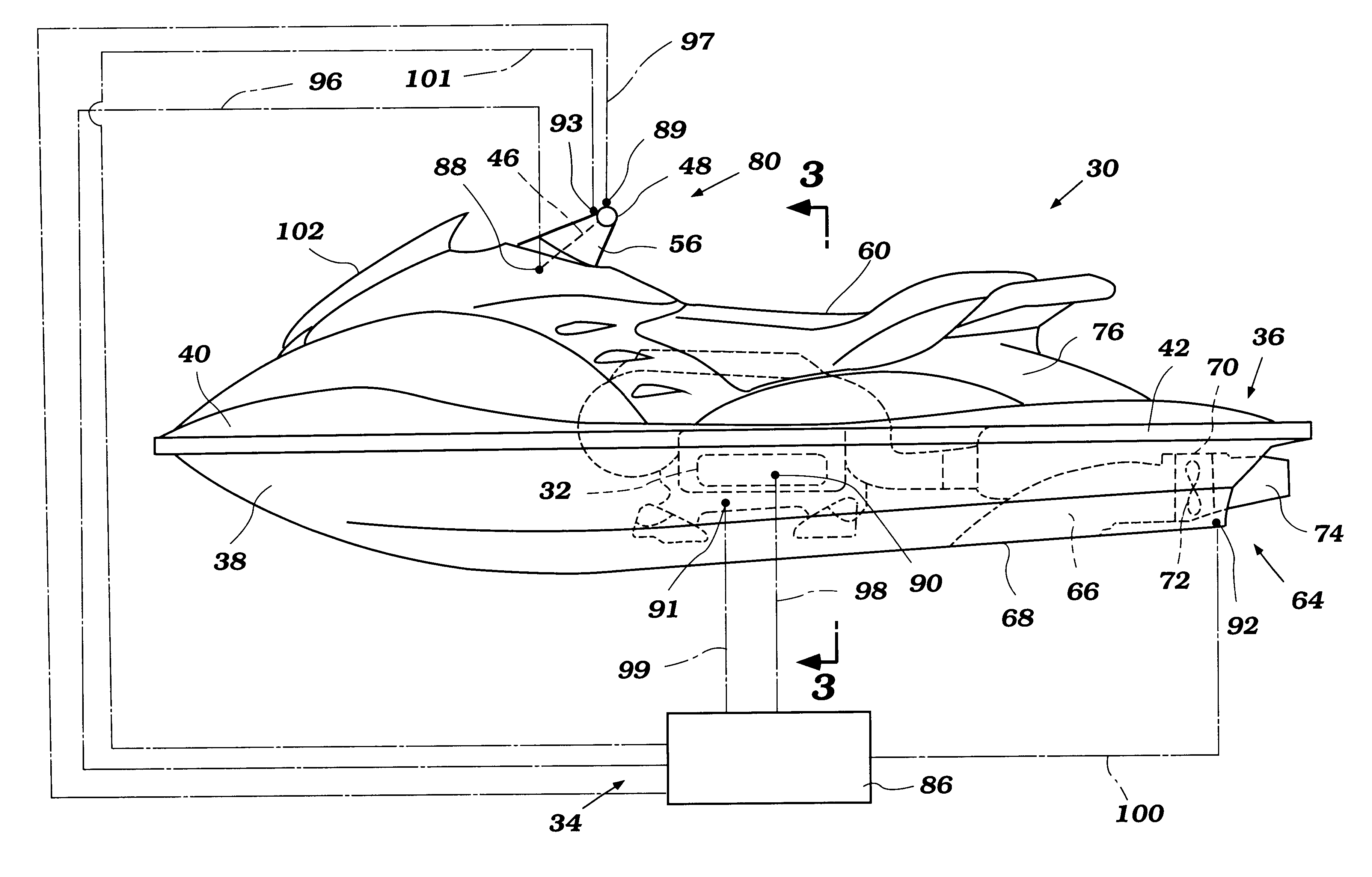
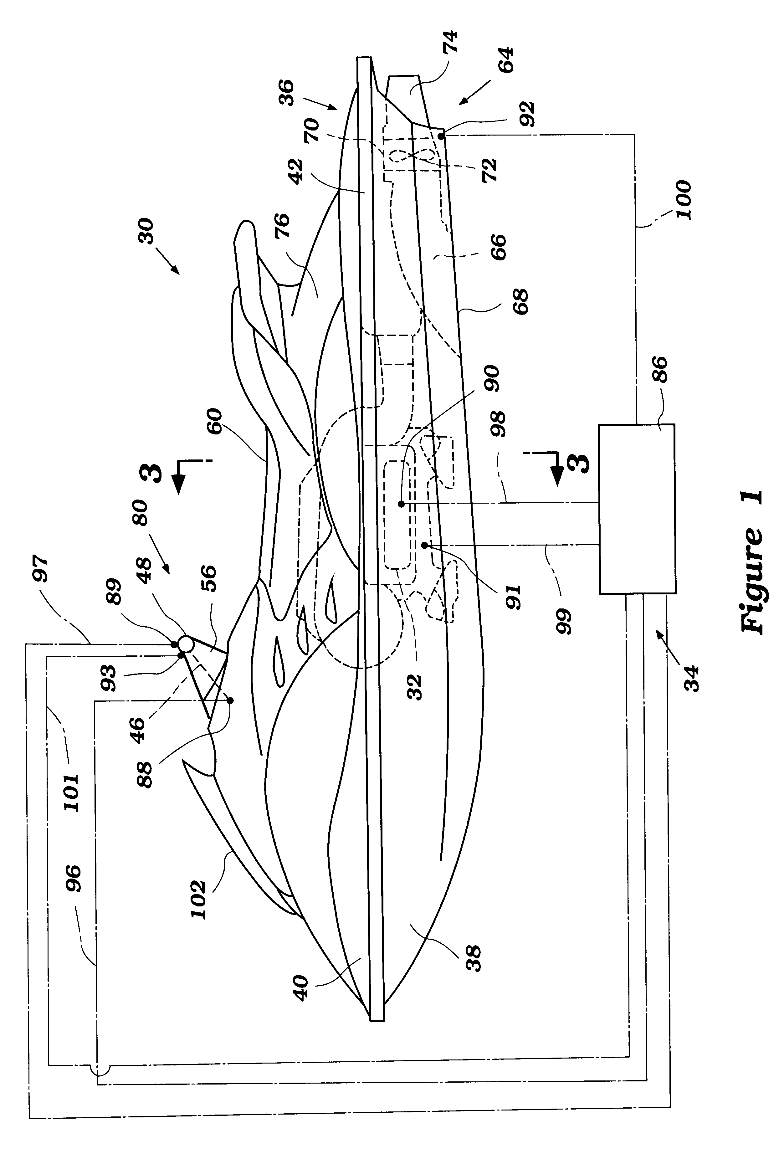
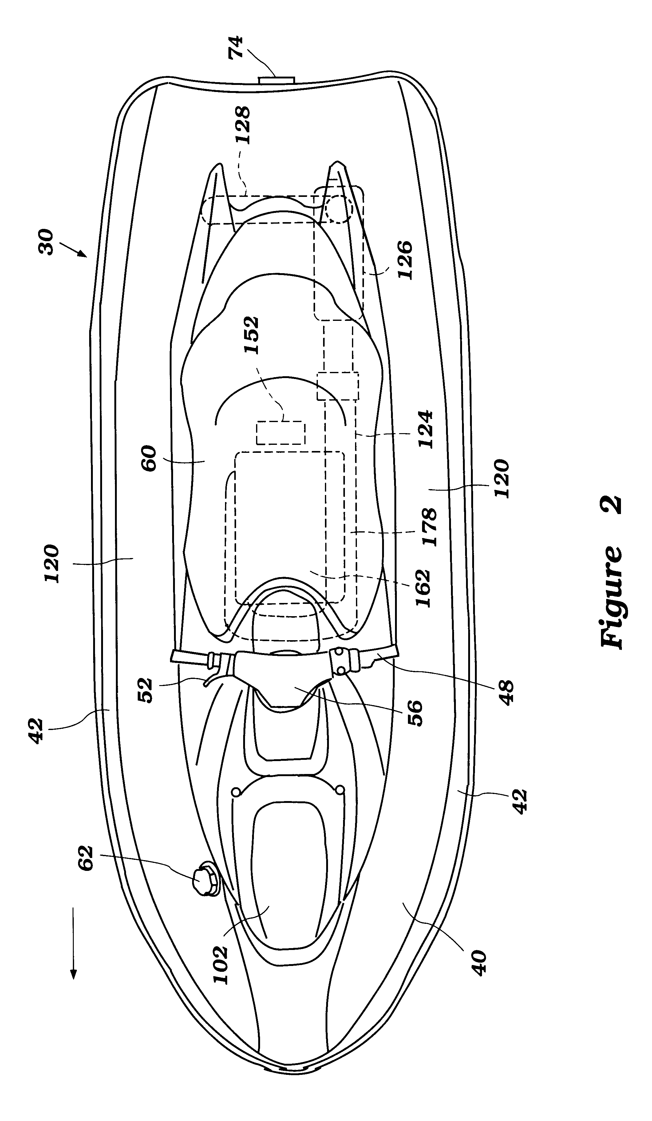
With primary reference to FIGS. 1 and 2, an overall configuration of a personal watercraft 30 will be described. The watercraft 30 employs an internal combustion engine 32 and an engine control system 34 configured in accordance with a preferred embodiment of the present invention. This engine control system 34 has particular utility with a personal watercraft and, thus, is described in the context of the personal watercraft. The control system, however, can be applied to other types of vehicles as well, such as, for example, small jet boats, all-terrain vehicles (ATVs), snowmobiles and the like.

The personal watercraft 30 includes a hull 36 generally formed with a lower hull section 38 and an upper hull section or deck 40. The lower hull section may include one or more inner liner sections to strengthen the hull or to provide mounting platforms for various internal components of the watercraft. Both the hull sections 38, 40 are made of, for example, a molded fiberglass reinforced re...


PUM


Abstract

A watercraft includes an improved engine control system that eases watercraft operation. The watercraft includes a propulsion device, such as a jet propulsion unit, and an engine that powers the propulsion unit. The engine control system is configured to limit engine speed under certain conditions.

Description

1. Field of the InventionThis invention relates to a control system for an engine of a watercraft.2. Description of the Related ArtPersonal watercraft have become very popular in recent years. This type of watercraft is quite sporting in nature and carries one or more riders. A hull of the personal watercraft commonly defines a rider's area above an engine compartment. An internal combustion engine powers a jet propulsion unit that propels the watercraft by discharging water rearward. The engine lies within the engine compartment in front of a tunnel, which is formed on an underside of the hull. The jet propulsion unit is placed within the tunnel and includes an impeller that is driven by the engine.A deflector or steering nozzle is mounted on a rear end of the jet propulsion unit for steering the watercraft. A steering mast with a handlebar is linked with the deflector through a linkage. The steering mast extends upwardly in front of the rider's area. The rider remotely steers the ...

Claims


Application Information

Patent Timeline
Patent Type & Authority Patents(United States)
IPC IPC(8): B63H21/22B63H21/00F02B61/00F02B61/04F02D9/02F02D11/02F02D11/10F02D29/02F02D41/04
CPCB63H21/213F02B61/045B63B2770/00B63B34/10
Inventor HATTORI, TOSHIYUKI
Owner YAMAHA MOTOR CO LTD
Why Eureka
Try Eureka