
Power supply for identification and control of electrical surgical tools

a technology for electrical surgical tools and power supplies, applied in the field of power supplies, can solve problems such as unintentional harm to patients, medical devices manufactured by one company, and medical devices that perform slightly differently than expected

Inactive Publication Date: 2004-02-24
MICROLINE SURGICAL INC
View PDF10 Cites 143 Cited by
  • Summary
  • Abstract
  • Description
  • Claims
  • Application Information

AI Technical Summary

Benefits of technology

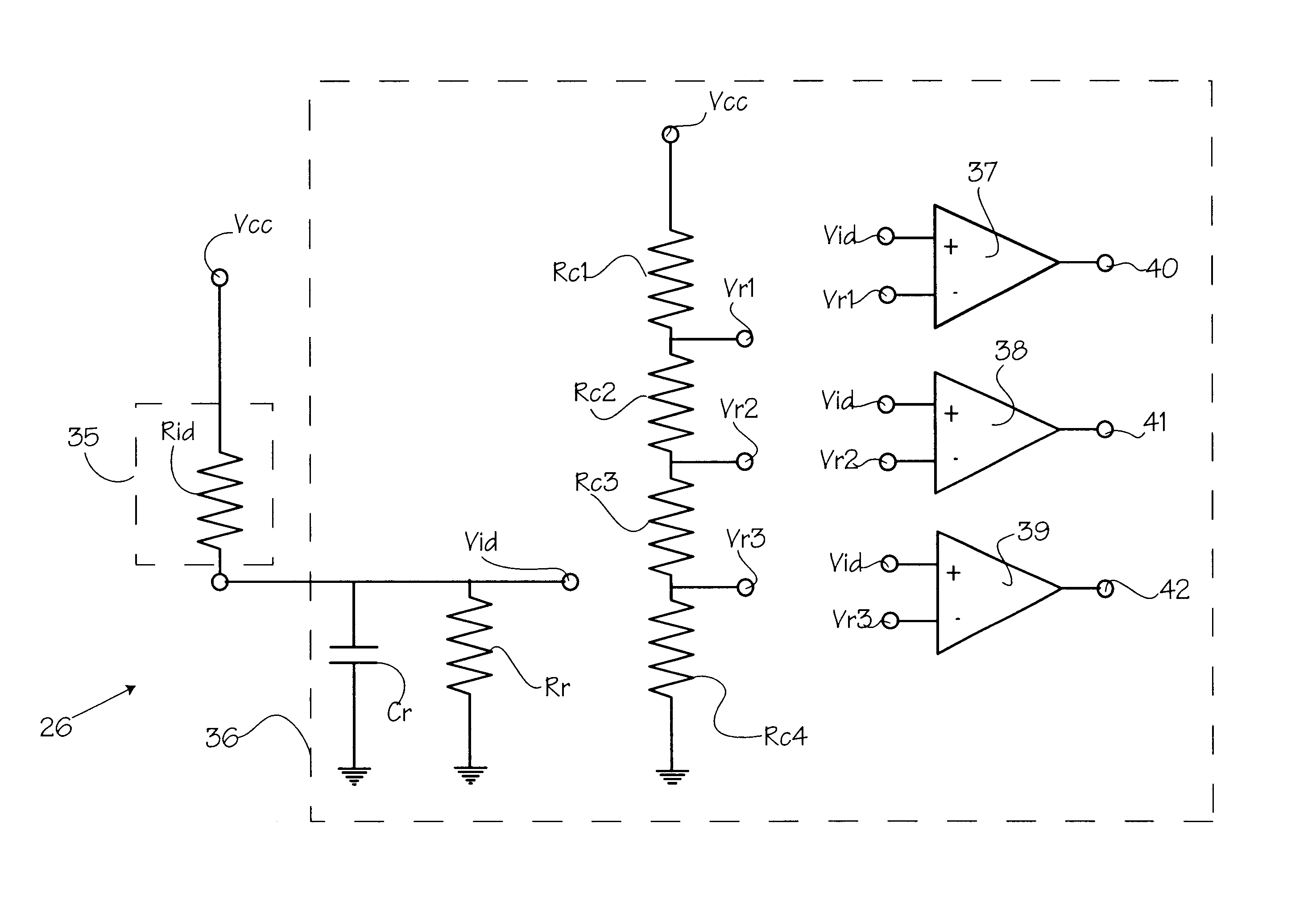
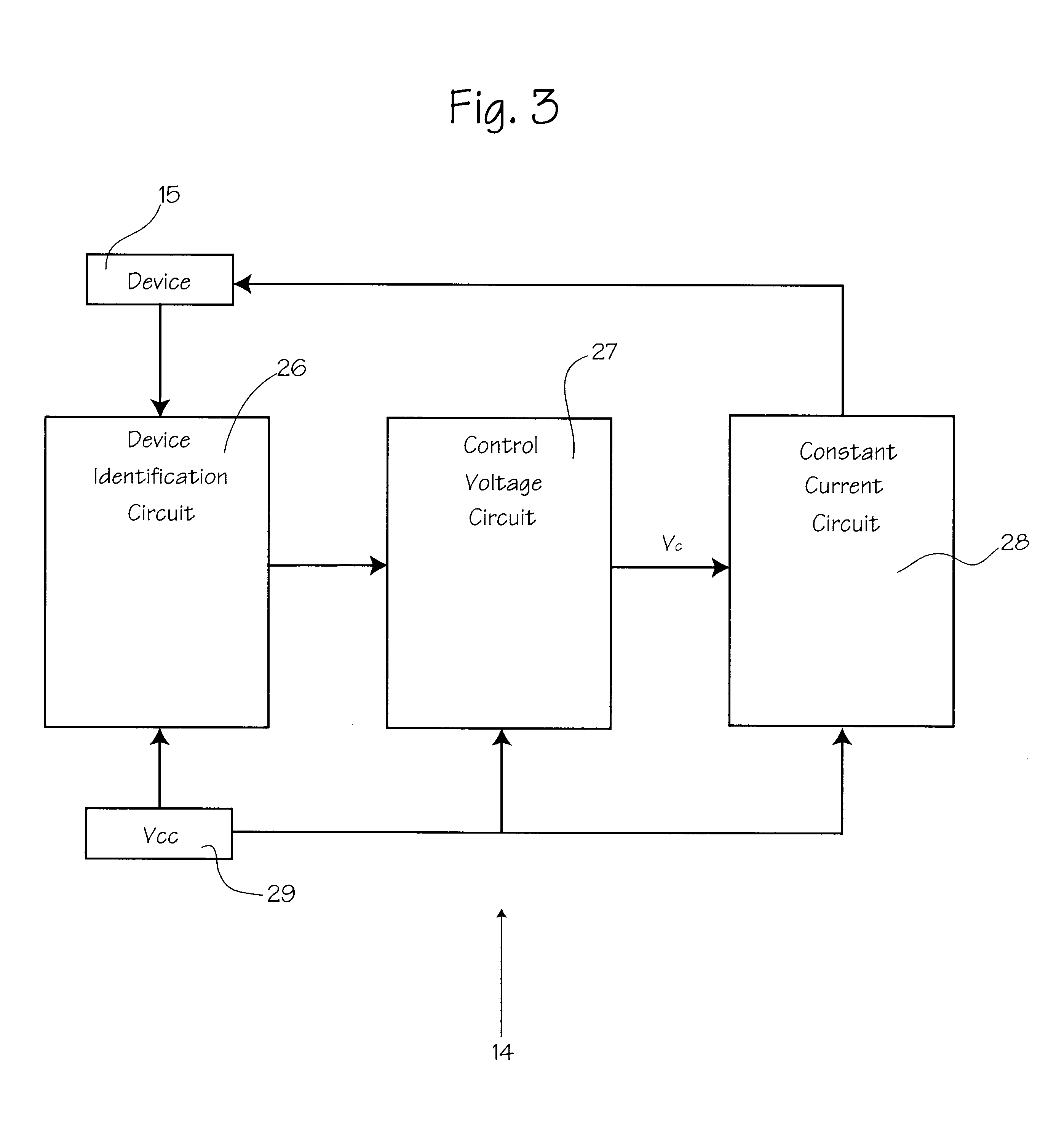
The patent describes a power supply for medical instruments, specifically electrical surgical tools, that can only operate with the specific tools for which it is designed. This is important because while some power supplies can operate with different kinds of medical instruments, it is difficult to ensure that the optimal amount of power is delivered to the tool. The power supply uses a device identification circuit and a constant current circuit to control the power output to the tool. The device identification circuit identifies whether the tool is designed to be used with that power supply. The constant current circuit provides the tool with the power it needs. The power supply is connected to an AC power source and has an on-off switch, an AC power connector, an LED power indicator, a control knob, and a hanger for suspending it. The power supply is also equipped with an interface board for adjusting the heat output of the cautery device. The technical effect of this invention is to ensure that electrical surgical tools operate only with the power supply for which they are designed, reducing the risk of harm to patients and ensuring optimal performance of the surgical procedure.

Problems solved by technology

The increase in the variety of surgical instruments has introduced a problem in medical-grade power supplies.
However, a medical device manufactured by one company may perform slightly differently than expected when the medical device is used in conjunction with a power supply from another company.
Since many medical procedures require precise control of the electrical properties of the medical device, a surgeon or doctor may unintentionally harm a patient when the surgeon uses a power supply and a medical device from different manufacturers.
When used in combination with such third party electrical surgical tools, it is not possible to ensure that the optimal amount of power is delivered to the tool.
Thus, the tool may not function as desired, with the result that the patient may be harmed.

Method used


Image

  • Power supply for identification and control of electrical surgical tools
  • Power supply for identification and control of electrical surgical tools
  • Power supply for identification and control of electrical surgical tools

Examples


Embodiment Construction

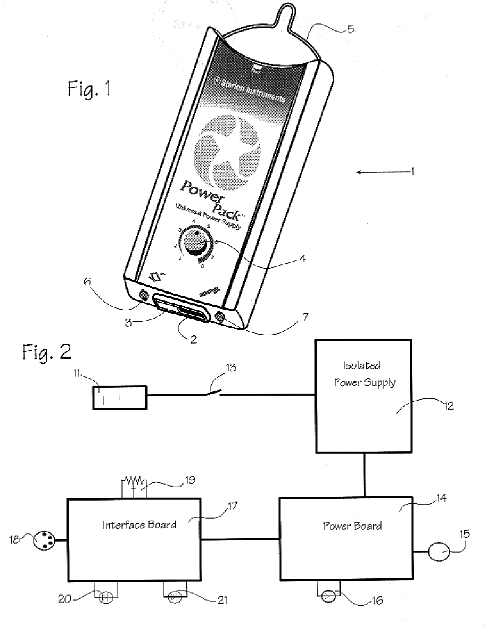
FIG. 1 illustrates a physical power supply box 1. The power supply box 1 is typically a non-sterile, reusable, AC powered device designed for use only with certain instruments, medical devices, electrosurgical devices, or other electrical surgical tools such as thermal cautery devices. The power supply is connected to an AC power source. The power supply has an on-off switch 2, an AC power connector 3, an LED power indicator 4, a control knob 5, and a hanger 6 suitable for suspending the power supply on a support object, such as an IV pole. The power supply is also equipped with an input 7 for an interface board, control board, or switches, and an output 8 to the medical instrument. The supply has input requirements of 100 to 240VAC at 50 to 60 Hz and at 80W, has a maximum output of 32VA, a no load voltage of 5V DC, and is operated at a duty cycle of about 5 seconds on and 10 seconds off. The output current is in the range of 2.4A to 4.4A, depending on which instrument is used and o...


PUM


Abstract

An electronic circuit for identifying an electrical surgical tool and for providing a selectable constant current appropriate to the identified electrical surgical tool.

Description

FIELD OF THE INVENTIONSThe devices described below relate to power supplies intended to supply electrical power to medical instruments.BACKGROUND OF THE INVENTIONSMany electrical surgical devices are provided in the form of electrical surgical tools, such as a thermal cautery device, which can be plugged into a separate power supply. Typically, the power supplied to the electrical surgical tool must be carefully controlled; thus, the power supply includes circuitry to convert available AC power to AC, RF, or DC power at the desired output power levels or frequencies. For example, Herzon, Thermal Cautery Surgical Forceps, U.S. Pat. No. 6,235,027 (May 22, 2001), shows thermal cautery forceps using a power supply to deliver a regulated current to the resistive heating elements in the forceps. Our own cautery instruments, such as the Starion.RTM. Thermal Cautery Forceps, which comprise forceps with resistive heating elements disposed on the grasping tips, are designed to work with our P...

Claims


Application Information

Patent Timeline
Patent Type & Authority Patents(United States)
IPC IPC(8): A61B18/08A61B18/04A61B18/00A61B18/14A61B19/00
CPCA61B18/08A61B18/14A61B2017/00482A61B2018/00988A61B2019/448A61B90/90
Inventor HOWELL, THOMAS A.
Owner MICROLINE SURGICAL INC
Learn More