
Filtering apparatus for filtering compressed air

a filtering apparatus and compressed air technology, applied in the direction of instruments, separation processes, dispersed particle filtration, etc., can solve problems such as data errors

Inactive Publication Date: 2004-03-09
FESTO AG & CO KG
View PDF10 Cites 25 Cited by
  • Summary
  • Abstract
  • Description
  • Claims
  • Application Information

AI Technical Summary

Benefits of technology

The electronic evaluating means preferably comprises a memory for storage of threshold values applying at least one filter means type. If the filter device is only designed for use with one single specific filter means type, the threshold values may be assigned in accordance with this one type of filter means. As an alternative it is possible for a plurality of different filter means types to be stored in the memory means, a selection means being present, which in a manner dependent on the actually installed filter means type renders possible a type-specific threshold value selection. This can for example be ensured by having manual settings, more especially by using a switch arrangement and / or using a potentiometer arrangement. However, a design is more convenient in which the filter device additionally has a detection means, which has means for the recognition of the currently installed filter type and which can generate a filter type specific electrical detection signal, which may be employed in the evaluating means for the type specific selection of threshold values. The detection means may for example have activating means provided on the filter means, such activating means cooperating directly or indirectly with the sensor means on the housing when the filter means is installed for producing a detection signal.
It is an advantage if the threshold values for one respective filter means may be set in a variable manner so that if necessary it is possible to make adaptations or with respect to further types of filter means to select particular specific threshold values.

Problems solved by technology

However, once in the operation of a compressed air supply network changes occur in the flow rate owing to switching loads on or off, this results in faulty data if the same set value applies with only one pressure differential threshold value.

Method used


Image

  • Filtering apparatus for filtering compressed air
  • Filtering apparatus for filtering compressed air
  • Filtering apparatus for filtering compressed air

Examples


Embodiment Construction

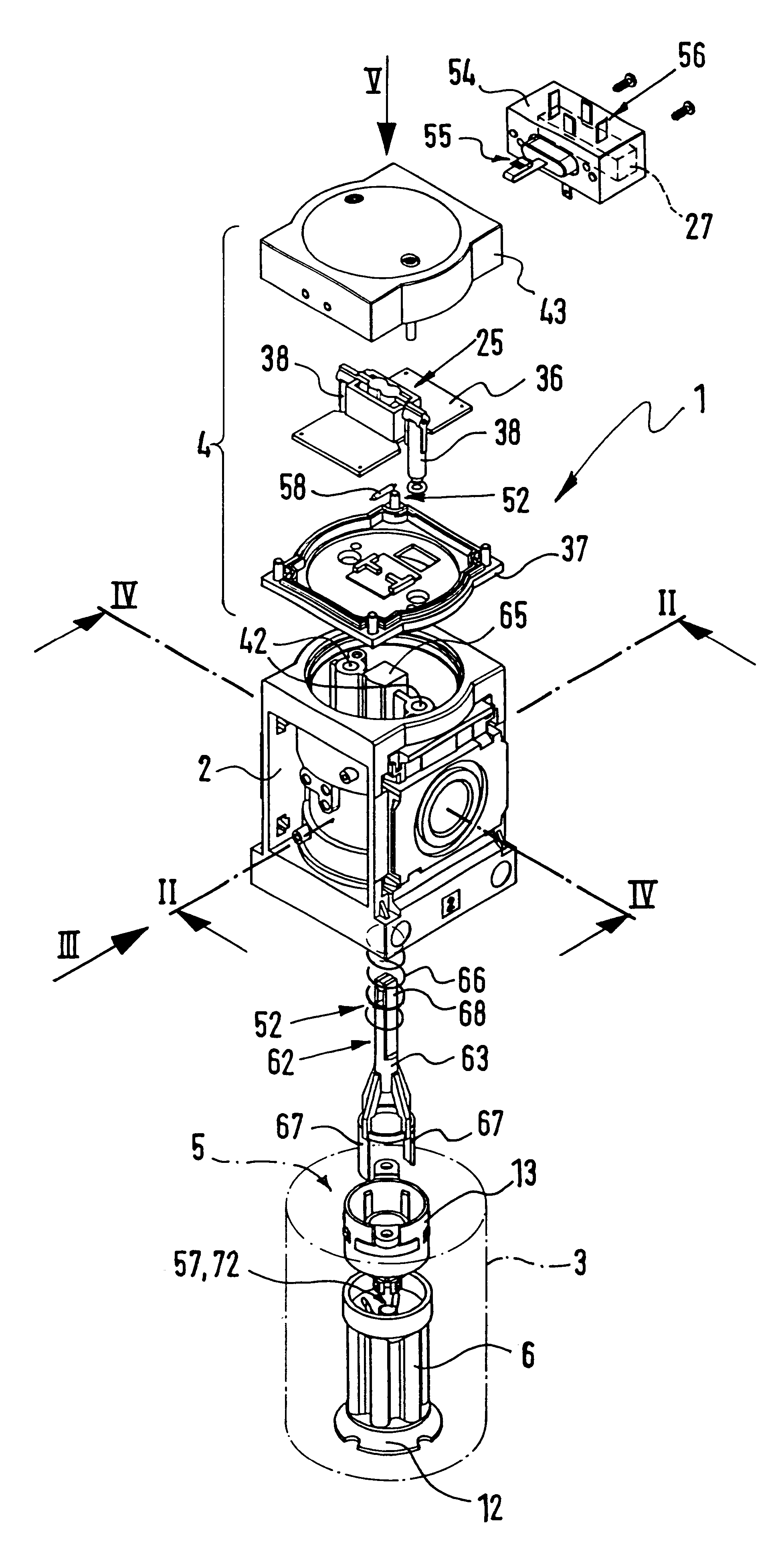
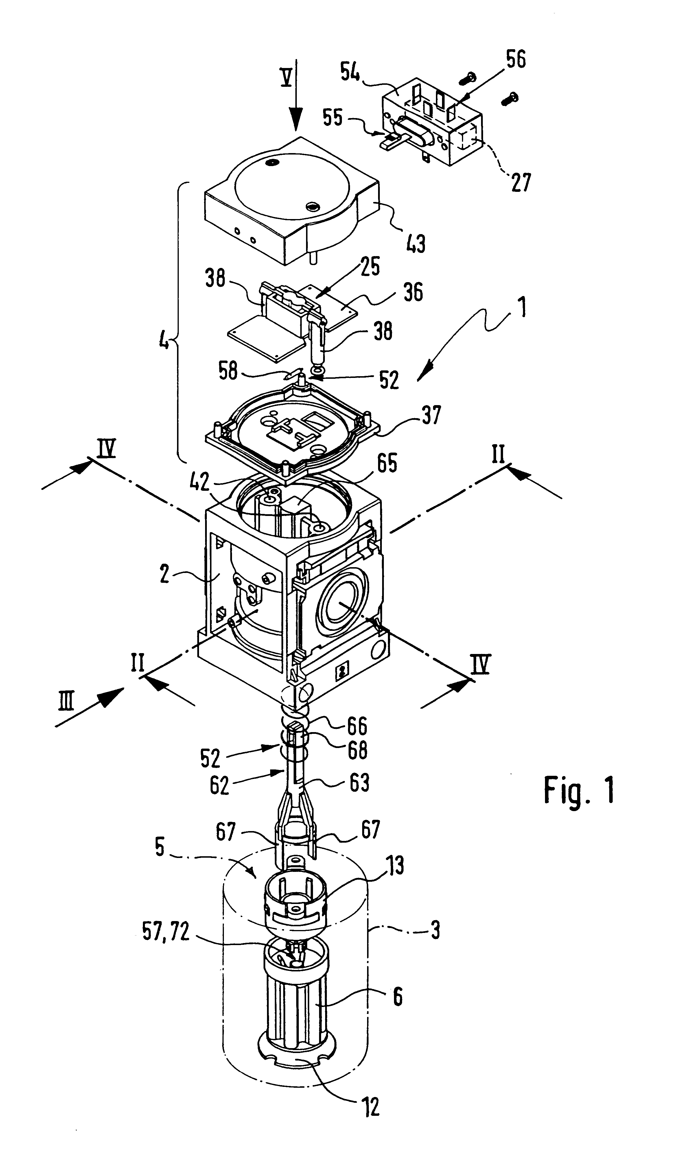
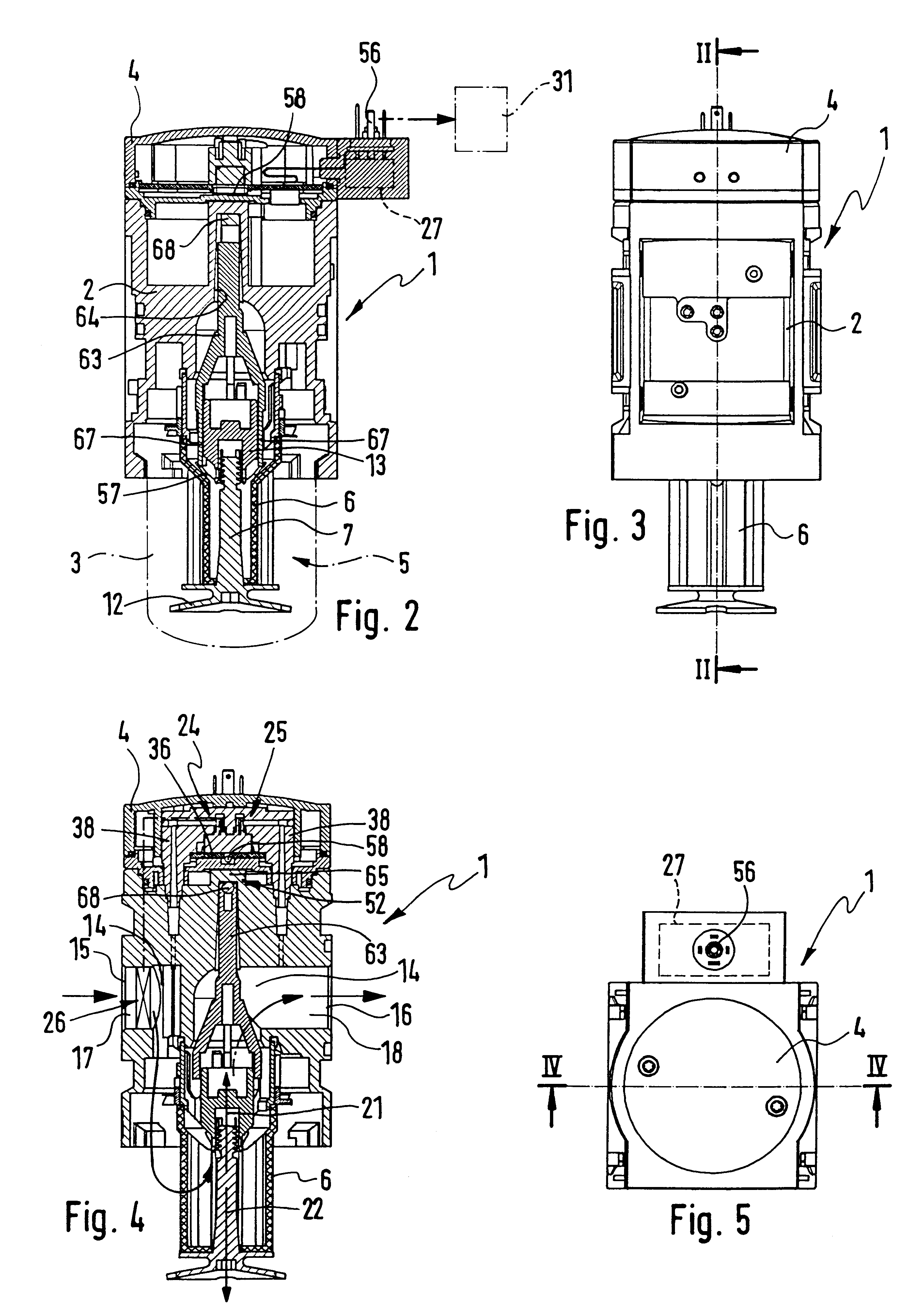
The filter device generally referenced 1 comprises a housing with, as an example, a block-like principal body 2, a beaker-like filter shell 3 secured to the bottom side thereof, and a head piece 4 mounted at the top on the principal body 2.

Together with the principal body 2 the filter shell 3 delimits a filter space 5, wherein a cartridge like filter means 6 is received in a replaceable manner.

The filter means 6, which has a tubular structure, is mounted at the bottom on the principal body 2 and detachably joined to it. For attachment in the present case an attachment screw 7 is employed, which is inserted from below through the central space 8 of the filter means 6, it acting on the filter means 6 from below at a disk 12 and its top end being screwed fixedly in the female thread of an attachment part 13 connected with the principal body 2 in its axial direction. The latter is in the working example attached as a separate component to the principal body 2 and has a sleeve-like form....


PUM

PropertyMeasurementUnit
Pressureaaaaaaaaaa
Flow rateaaaaaaaaaa
Threshold limitaaaaaaaaaa

Abstract

A filter device for filtering compressed air having recognition means (24), which render possible recognition of the degree of contamination of the filter means (6) fitted. The recognition means (24) comprise a pressure differential sensor means (25) responsive to the pressure differential at the filter means (6) and a flow rate sensor means (26) responsive to the flow rate. Furthermore there is an electronic evaluating means (27) for linking the detected pressure differential values and the flow rate values to give a condition value relevant for the degree of contamination of the filter means (6) and to be compared with predetermined threshold values.

Description

FIELD OF THE INVENTIONThe invention relates to a filter device for filtering compressed air comprising a principal fluid duct extending between an inlet and an outlet and divided by filter means, through which compressed air flows in operation, into an inlet flow section and an outlet flow section.BACKGROUND OF THE INVENTIONFilter devices of this type, as are disclosed for instance in the assignee's "Pneumatic-Katalog 97 / 98", page 9.3 / 15-1 as a rule comprising a housing with a principal body having the inlet and the outlet and a vessel-like filter shell fixed thereto in a detachable manner. In the space defined between the principal body and the filter shell a replaceable and preferably cartridge-like filter means is sealed, which divides up the principal fluid duct extending between the inlet and the outlet into an outlet flow section associated with the inlet and an inlet flow section associated with the outlet. Compressed air supplied by way of the inlet is cleaned on flowing thr...

Claims


Application Information

Patent Timeline
IPC IPC(8): B01D46/44B01D46/46
CPCB01D46/0086B01D46/446B01D46/46
Inventor FRANZ, JOCHENGEBAUER, GUNTER
Owner FESTO AG & CO KG
Learn More