Ophthalmologic surgical microscope having focus offset

a surgical microscope and focus offset technology, applied in the field of ophthalmologic surgical microscopes, can solve the problems of difficult for surgeons to sharply adjust the surgical microscope onto different planes in the eye, and the inability to ensure the functioning of the autofocus system in each ey

Active Publication Date: 2009-06-30
CARL ZEISS SURGICAL
View PDF13 Cites 13 Cited by
  • Summary
  • Abstract
  • Description
  • Claims
  • Application Information

AI Technical Summary

Benefits of technology

[0013]It is an object of the invention to provide a viewing assist for carrying out surgical procedures on a human eye wherein the surgeon is enabled to view rapidly and sharply different planes or levels of the eye.
[0016]In another embodiment of the invention, an input unit is assigned to the focus offset adjusting unit which makes it possible for an operator to select a desired value for an offset of the focus of the objective arrangement from a focusing state which the focus offset adjusting unit sets. In this way, the possibility is afforded to select section planes of a patient eye which are to be sharply viewed.
[0018]In a further embodiment of the invention, an ophthalmoscopic magnifier is provided which can be positioned selectively in the viewing beam path of the ophthalmologic surgical microscope or outside of the viewing beam path of the ophthalmologic surgical microscope. Switching means are provided which activate the autofocusing system when positioning the ophthalmoscopic magnifier outside of the viewing beam path. In this way, a surgeon rapidly obtains sharp images from the anterior chamber and the ocular fundus during surgical procedures on the eye.
[0022]In a further embodiment of the invention, selection means are provided for an image zone whose contrast can be determined with the means for determining the image contrast. In this way, the surgeon can select structures on the eye whose image is selected for an autofocusing operation.
[0023]According to another feature of the invention, a focus offset adjusting unit is provided which outputs a focusing offset signal to an adjusting unit for the objective arrangement in order to focus the objective arrangement utilizing an adjustment by a predetermined focus offset starting from a first focusing state of the objective arrangement wherein the objective arrangement is focused on a first object plane to a second focusing state wherein the objective arrangement is focused on a second object plane. An input unit is assigned to the focus offset adjusting unit which enables an operator to input a desired value for a predetermined focus offset. In this way, it is possible during eye surgery to manually adjust the ophthalmologic surgical microscope onto the iris of a patient eye and to then automatically displace the focus plane of the arrangement into the interior of the patient eye.

Problems solved by technology

This makes it difficult for a surgeon to sharply adjust the surgical microscope onto different planes in the eye whereat surgery is taking place.
However, if an organ, which is transparent over wide regions such as the human eye, is examined, the functioning of an autofocus system is not guaranteed in each case because, not in all levels of the eye are there structures which have a high contrast or scatter a scanning light beam.

Method used


Image

  • Ophthalmologic surgical microscope having focus offset
  • Ophthalmologic surgical microscope having focus offset
  • Ophthalmologic surgical microscope having focus offset

Examples


Embodiment Construction

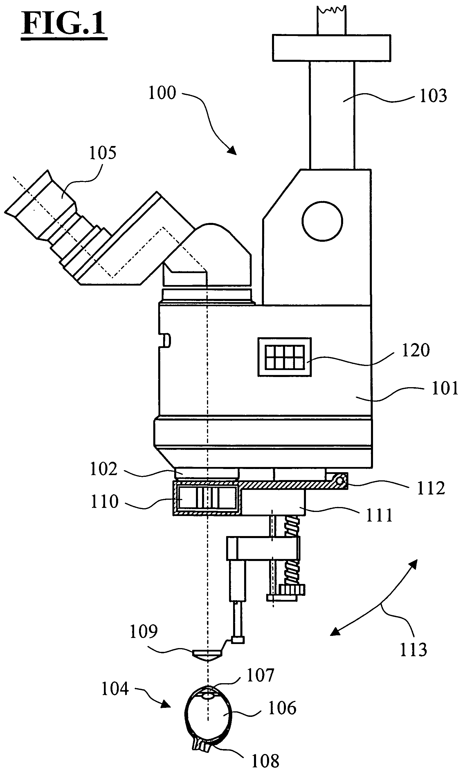
[0034]In FIG. 1, an ophthalmic surgical microscope 100 is shown as a microscope arrangement for viewing an object in the form of a human eye. The ophthalmic surgical microscope 100 includes a surgical microscope base body 101 in which a microscope main objective system 102 with a zoom system is accommodated. The microscope main objective 102 is focusable by means of a drive. The surgical microscope base body 101 is held by a carrier arm 103 on a surgical microscope stand. In this way, a physician performing a surgical procedure is enabled to position the ophthalmic surgical microscope 100 in a desired viewing position relative to the eye 104 of a patient. The ophthalmic surgical microscope 100 is configured as a stereomicroscope and has a binocular tube 105 via which the operating physician can view an operating area magnified via the zoom system and the microscope main objective system 102.

[0035]The patient eye 104 is a spatially extended organ having a vitreous body 106 which is a...


PUM


Abstract

A microscope arrangement (200) is for viewing an object or an intermediate image, which is generated by an object, especially in microsurgery. The microscope arrangement (200) includes an objective arrangement (201) having an object plane (209) for arranging the object or intermediate image (210) to be viewed. The microscope arrangement has a focus offset adjusting unit (260) which outputs a focusing offset signal in order to defocus in a defined manner the objective arrangement relative to a focusing state.

Description

CROSS REFERENCE TO RELATED APPLICATION[0001]This application claims priority of German patent application no. 10 2005 011 781.3, filed Mar. 11, 2005, the entire content of which is incorporated herein by reference.FIELD OF THE INVENTION[0002]The invention relates to an ophthalmologic surgical microscope for microsurgery for viewing an object or an intermediate image, which is generated by the object, wherein an objective arrangement is provided which can be adjusted to focus on an object plane in which an object or intermediate image is disposed which is intended to be viewed.BACKGROUND OF THE INVENTION[0003]An ophthalmologic surgical microscope of the kind referred to above is known from German patent publication DE 35 39 009 A1. There, an ophthalmologic surgical microscope is described which is equipped with an ancillary module which includes an ophthalmoscopic magnifier and a system for beam transposition and image reversion. The surgical microscope has a microscope main objectiv...

Claims


Application Information

Patent Timeline
Patent Type & Authority Patents(United States)
IPC IPC(8): G02B21/00
CPCG02B21/0012G02B21/244A61B3/13
Inventor MOELLER, GERHARDREIMER, PETERANDREWS, PETER
Owner CARL ZEISS SURGICAL
Why Eureka
Try Eureka