Wavelength-division multiplexed optical transmission system

a transmission system and wavelength channel technology, applied in wavelength-division multiplex systems, multiplex communication, baseband system details, etc., can solve the problems of serious deterioration in transmission, no guarantee of data correlativity among a plurality of wavelength channels, and deterioration of transmitting characteristics, so as to suppress the occurrence of abnormally large xpm and xgm. , the effect of reducing the correlativity

Inactive Publication Date: 2007-07-19
NEC CORP
View PDF15 Cites 19 Cited by
  • Summary
  • Abstract
  • Description
  • Claims
  • Application Information

AI Technical Summary

Benefits of technology

[0025] To solve the above-expressed problems, it is an object of the present invention to provide a wavelength-division multiplexed optical transmission system capable of keeping the correlation of data patterns among wavelength channels to the low level, preventing large XPM and XGM from occurring when the correlation is strong, and assuring a stable transmitting quality.
[0030] The wavelength-division multiplexed optical transmission system of the present invention also has a system for making it possible to select a pseudo random pattern used for scrambling from among a plurality of kinds of the pseudo random pattern, and for mutually differing data patterns transmitted upon inputting no transmitting data among wavelength channels.
[0032] Accordingly, according to the wavelength-division multiplexed optical transmission system of the present invention, it is possible to decrease the correlativity among the channels whose wavelengths are multiplexed and suppress the occurrence of abnormally large XPM and XGM.

Problems solved by technology

However, a problem might arise, when wavelength-multiplexing the SONET / SDH signal which took no account of the wavelength multiplexing transmission as it is.
In particular, according to a conventional SONET / SDH system, there is a problem to have no guarantee on no correlativity for data among a plurality of wavelength channels which are transmitted in parallel in the optical transmitting line.
In the case where the data among the parallel transmitted channels is strongly correlative, it is dangerous to cause the serious deterioration in transmission.
Particularly, the XPM is phase modulation caused by a signal having no correlation with information which the XPM itself has, and thus the transmitting characteristic is deteriorated certainly.
However, if all of the channels except for any noticed channel (referred to as λ3, herein) have the same data and same phase, as shown in FIG. 15, an abnormally large XPM occurs in the noticed channel.
Although such a situation should be prevented as much as possible, there is a great of risk for the conventional apparatus to get into such a situation.
The data matching hardly occurs upon normal operation and, however, there is a possibility that the data matching is caused exceptionally, such as alarm transferring case.
As another problem which arises by making the frame phase similar, there is a cross gain modulation effect (XGM: Cross Gain Modulation) in an optical amplifier in these days.
Corresponding thereto, there is a problem how low frequency component is included in the transmitted signal.
On the contrary, if the frame phases are made uniform, it is remarkably dangerous to transfer the intensity fluctuation to a channel of a channel except for the noticed channel.
Actually, if making a channel excluding the noticed channel have the same data and the same frame phase in an examining system as shown in FIG. 11, a serious bit error rate degradation is observed in the noticed channel.

Method used


Image

  • Wavelength-division multiplexed optical transmission system
  • Wavelength-division multiplexed optical transmission system
  • Wavelength-division multiplexed optical transmission system

Examples


first embodiment

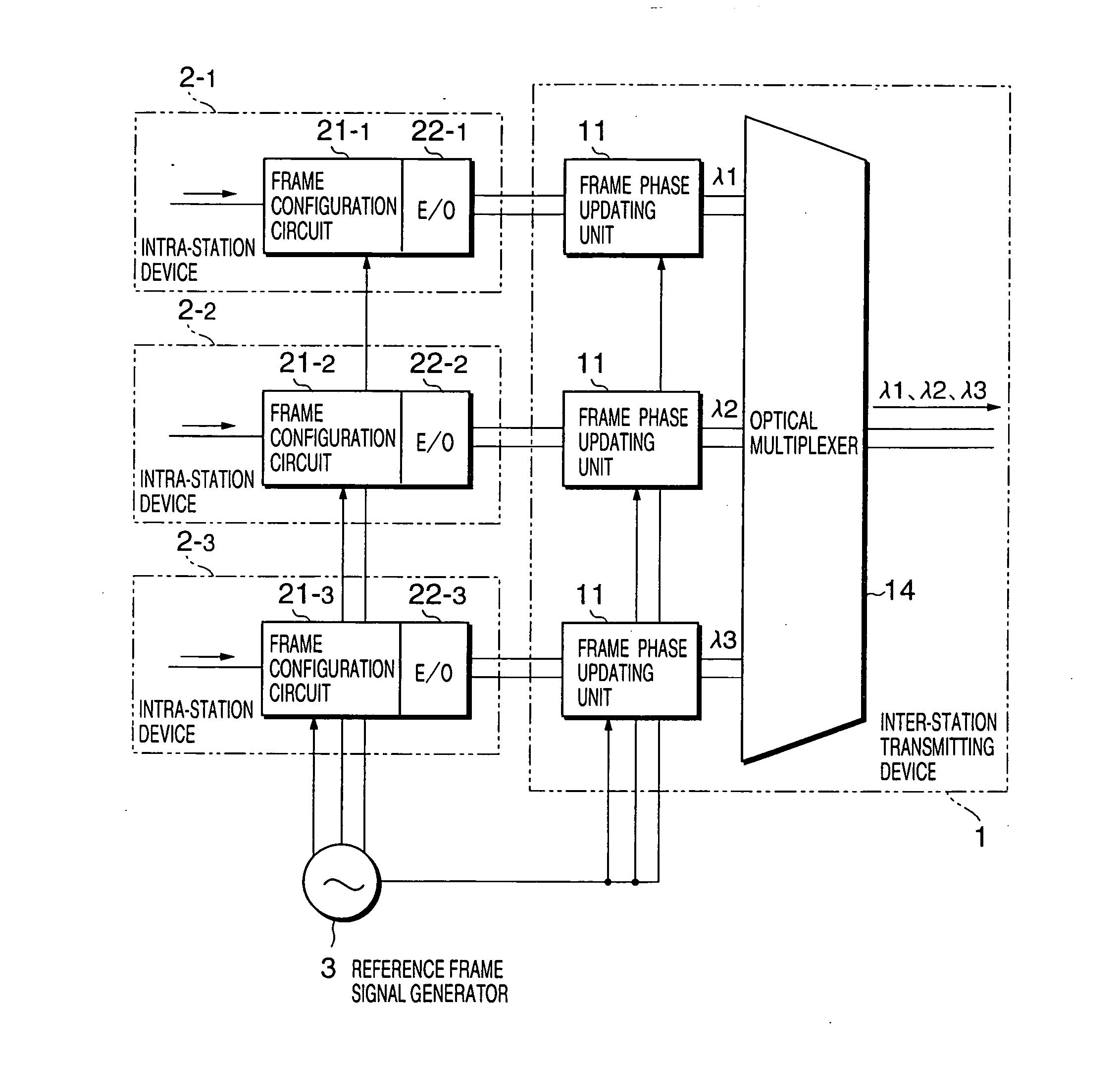
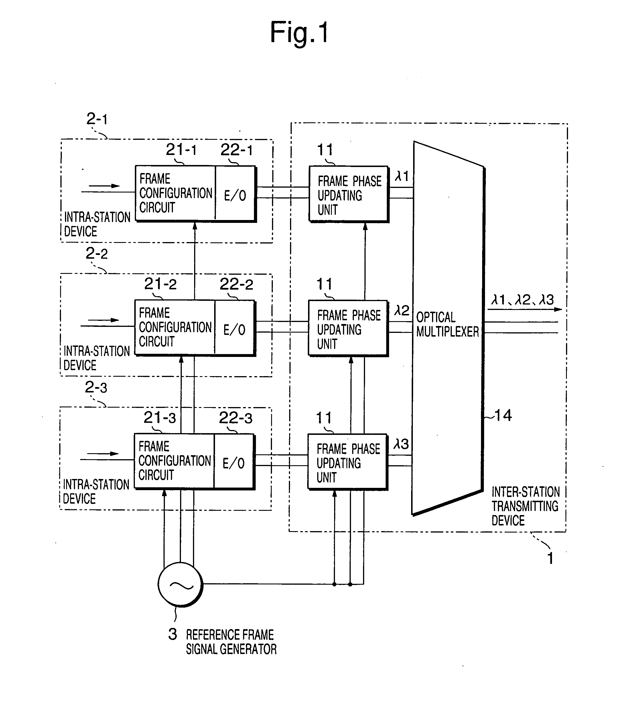
[0054] The next description turns to embodiments of the present invention with reference to the drawings. FIG. 1 is a block diagram showing a construction on a transmission side in a wavelength-division multiplexed optical transmission system according to the present invention, and corresponds to the construction on a transmitting side in an optical transmission system including a transmitter Tx100 and a receiver Rx200, which is connected via an optical transmitting line 300 made up of an optical fiber shown in FIG. 17.

[0055] Referring to FIG. 1, the transmitting side in the wavelength-division multiplexed optical transmission system according to the first embodiment of the present invention comprises an inter-station transmitting device 1 and intra-station devices 2-1 to 2-3. It is noted to schematically indicate a portion wherein optical signals outputted from the intra-station devices 2-1 to 2-3 are wavelength-multiplexed and transmitted to an optical fiber transmitting line (not...

third embodiment

[0100] According to the present invention, if changing the scrambling pattern, only execute the scrambling process by employing the scrambling data generating unit 71 in the scrambling circuit 7.

[0101] Accordingly, in proportion to the definite function, it is able to simplify the signal processing circuit and reduce costs. When configuring the frame for error correcting code herein, the third embodiment of the present invention can be embodied by adding the frame configuration to the processing circuit, and also can suppress the increase in the number of parts. The scrambling circuit 7 can be used for the inter-station transmitting device 1, etc., as shown in FIG. 1.

[0102] In order to descramble the data on a receiving side (not shown), the scrambling pattern used on the transmitting side must be known. Mainly, there are two methods of communicating the scrambling pattern. According to one communicating method, by embedding information indicative of a pattern kind of non-scrambled...

fourth embodiment

[0122]FIG. 10 is a diagram for illustrating a dummy data pattern control method according to the present invention. Referring to FIG. 10, the present embodiment is one example obtained by applying the present dummy data pattern control method to a switch for switching the dummy data pattern to the dummy data patterns included in frame configuration circuits 41-1 to 41-3 in a transmitter for transmitting optical signals which are wavelength-multiplexed to the same fiber.

[0123] That is, the present embodiment comprises: the frame configuration circuits (switches for switching data to the dummy data pattern) 4-1-1 to 41-3; E / Os 42-1 to 42-3; a dummy data pattern controller 43; and an optical multiplexer 44.

[0124] The dummy data pattern controller 43 receives managing information such as the number of wavelength, wavelength separation between channels, transmitting line dispersion value of the optical signal which is wavelength-multiplexed to the same fiber, calculates the dummy data p...


PUM


Abstract

A wavelength-division multiplexed optical transmission system to keep the correlation of data patterns among wavelength channels to a low level, assuring a stable transmitting quality. The wavelength-division multiplexed optical transmission system has any of a frame phase changing circuit for mutually differing transmitting frame phases between at least two or more wavelength channels, a scrambling circuit using a data scrambler based on a pseudo random pattern for mutually differing scrambling patterns between two or more wavelength channels, or a dummy data generating circuit for mutually differing invalid data patterns between at least two or more wavelength channels in a wavelength channel group transmitted through the same optical fiber transmitting line when transmitting meaningless data.

Description

BACKGROUND OF THE INVENTION [0001] 1. Field of the Invention [0002] The present invention relates to a wavelength-division multiplexed optical transmission system, more particularly, to a wavelength-division multiplexed optical transmission system which is capable of reducing inter-channel correlation that may cause a serious transmission quality degradation. [0003] 2. Description of the Related Art [0004] In these days, according to digital standardized information communication used for an optical fiber transmission system, there is widely utilized a frame synchronous communication system which is called an SONET (Synchronous Optical Network) / SDH (Synchronous Digital Hierarchy) [0005] According to the SONET / SDH standard, relative phase difference information between a data signal and a frame phase, what is called a pointer, is given to an overhead area in a frame and transmitted, thereby enabling the change in phase difference between the data signal and the frame phase. [0006] Si...

Claims


Application Information

Patent Timeline
Patent Type & Authority Applications(United States)
IPC IPC(8): H04J14/02H04J14/08H04B10/2557H04J3/00H04J3/06H04J3/16H04J14/00H04L25/14
CPCH04J3/1611H04L25/14H04J2203/0076H04J14/02
Inventor YANO, YUTAKA
Owner NEC CORP
Why Eureka
Try Eureka