Goniometer

a goniometer and design technology, applied in the field of goniometer design, can solve the problem that the arrangement does not provide negligible eccentricity

Inactive Publication Date: 2004-03-16
MAURO GEORGE
View PDF10 Cites 16 Cited by
  • Summary
  • Abstract
  • Description
  • Claims
  • Application Information

AI Technical Summary

Benefits of technology

The design is an improvement over the current designs where shorter rotational travels (minor adjustments, 3-20.degree.) and smooth sensitive and repeatable action are required, but exact long range eccentricity and load capacity are not, such as in fiberoptic alignment. The present invention provides goniometers which are considerably cheaper, and possibly better than using precision roller ways. It employs three or four bearing balls, two riding in counter-v-grooves at least one of which is a V-groove opposed to a non-constraining flat surface, to give complete kinematic stability in every aspect except rotation.
The design with the three ball bearings is the simplest and this affords a three-point contact for low load requirements.
A possible further version employs pre-fabricated bearing races, cut into sections for partial rotation, as separate parts attached to receiving areas in the goniometer body, rather than machining them right in. This allows the design to eliminate the third groove pair, while the second groove pair manages its former operation by having the attributes of both groove pairs built into one.
Another embodiment, using the four ball system, is one in which the cylinder pair is "very long as compared to the diameter, and also in 2 sections. This would allow a very lightweight off-axis tilt table.
In a preferred three ball embodiment, three balls, between the rotor and the support base, are constrained to follow arcuate paths to allow said rotation of the rotor, relative to the support base, the three balls being constrained to be spaced apart in at least two dimensions wherein there are first and second said spaced apart arcuate paths, the first said arcuate path being defined by an arcuate V-groove defined by one of the rotor and support base and a non-constraining arcuate flat surface defined by the other of the rotor and support base, one said ball being disposed in the first said arcuate path in contact with the rotor and the support base and two balls being disposed spaced apart in the second arcuate path constrained by opposed V-grooves forming the second arcuate path, thereby to ensure a three point spaced apart support contact between the rotor and the support base.

Problems solved by technology

These arrangements do not provide negligible eccentricity coupled with smooth sensitive action as is required i.e. for fiber optic alignment.

Method used


Image

  • Goniometer
  • Goniometer
  • Goniometer

Examples


Embodiment Construction

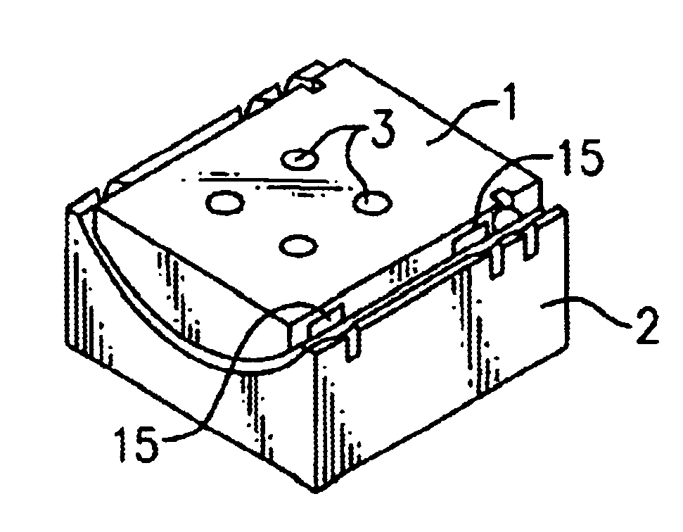
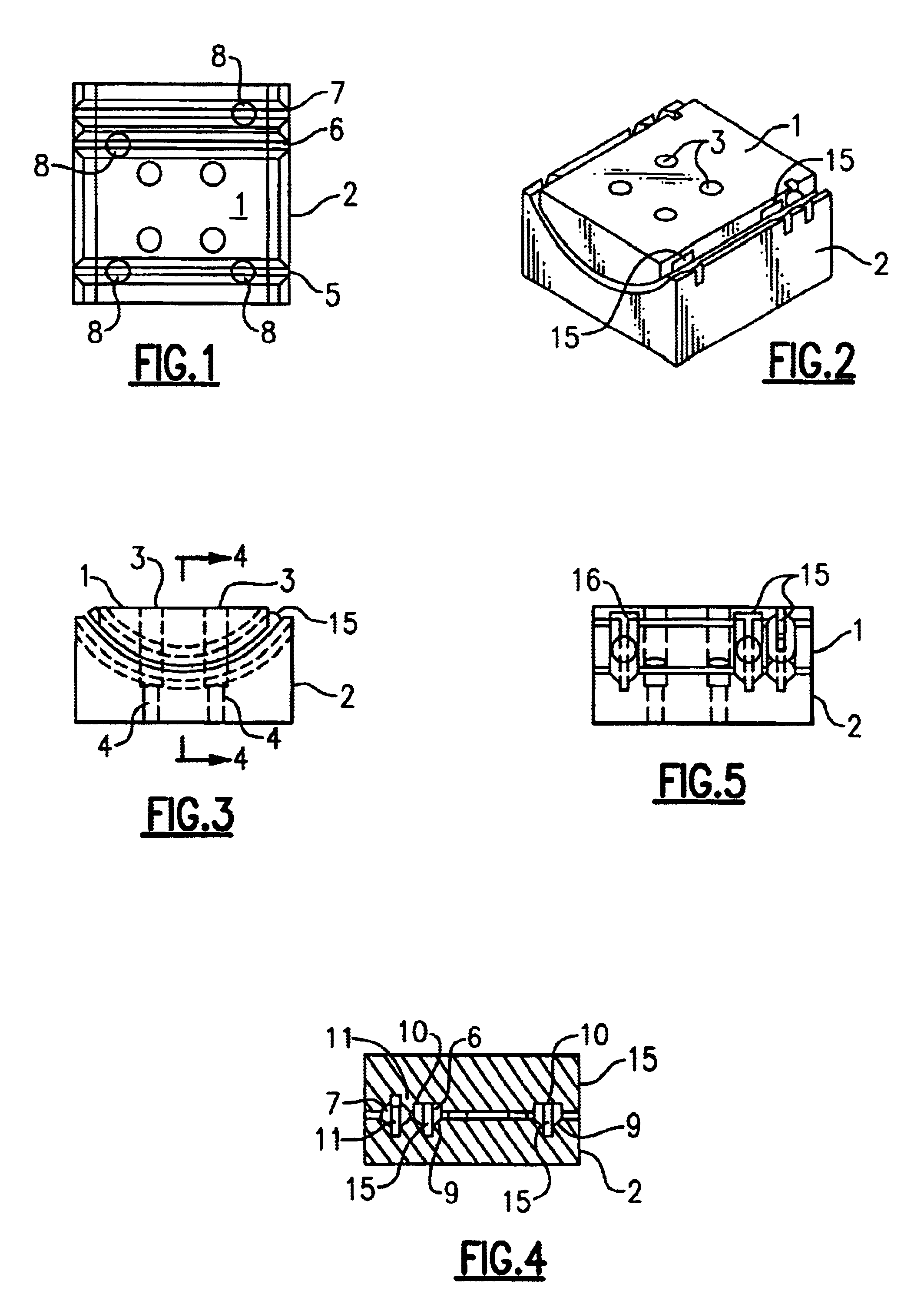
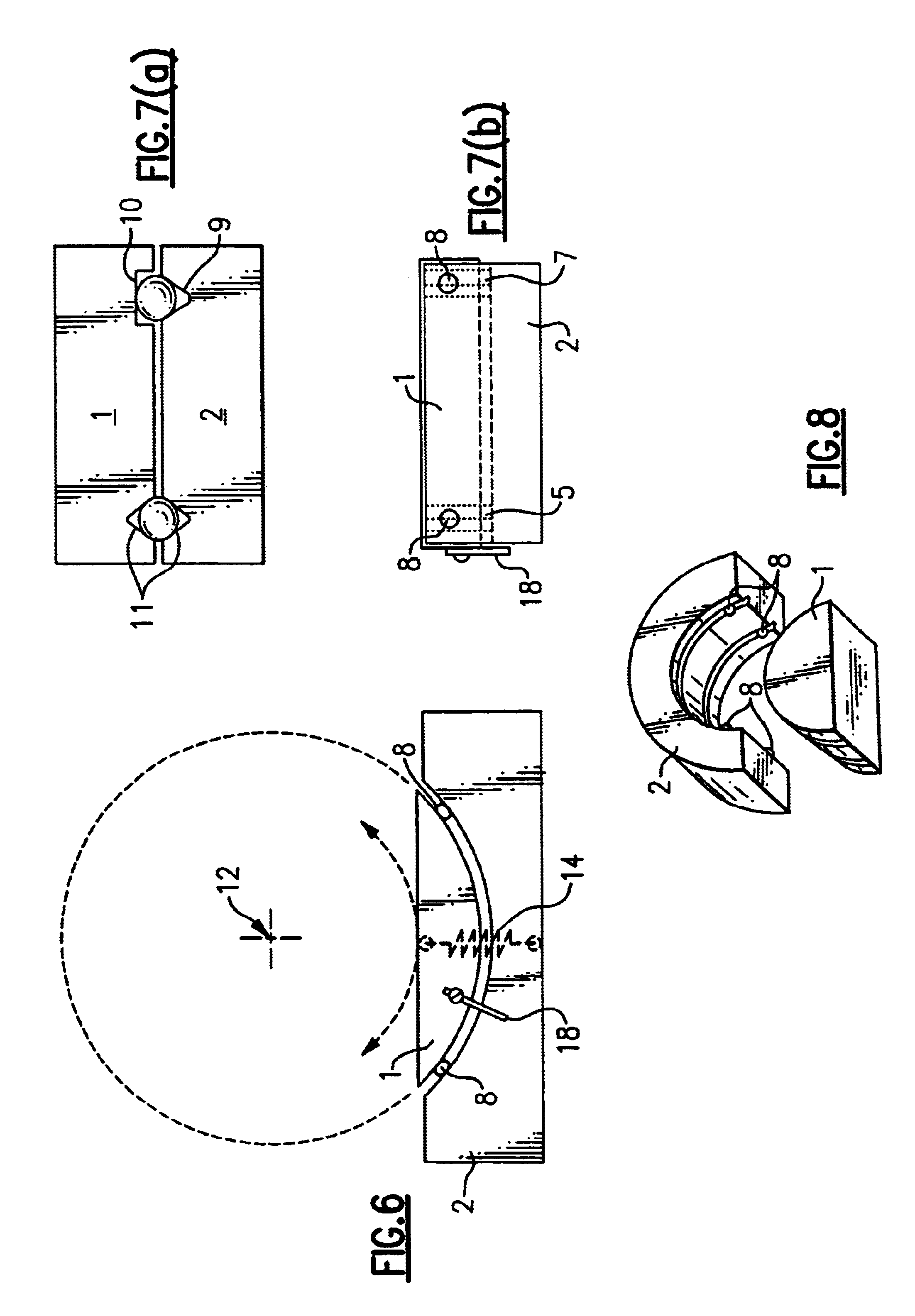
Referring to FIGS. 1-5 a rotor 1 is supported for limited rotation by a base 2. Through holes 3 are provided in the rotor 1 to allow access to base mounting holes 4 by which screws may mount the base 2 to a support structure. In this embodiment three parallel arcuate tracks 5, 6 and 7 engage four balls 8 with tracks 5 and 6 having opposed arcuate surfaces as shown in FIG. 12 and track 7 having an arcuate surface as shown in FIG. 13. In this arrangement the tracks 5 and 6 comprise a arcuate V-groove 9 in base 2 laterally locating the associated balls 8 and in engagement with a flat matching arcuate surface 10 defined by rotor 1 and track 7 has opposed arcuate V-grooves 11 laterally locating the associated ball 8 and in engagement with each other freedom of movement along these grooves as hereinafter described. Three of the balls 8 are arranged with two spaced apart in track 5 and one in track 6 all three being located by cages 15 while the fourth ball 8 is located in track 7 and is f...


PUM


Abstract

A goniometer comprising a rotor and a support base having therebetween three or four balls or rollers constrained to follow arcuate paths to provide rotation of the rotor, relative to the support base, about an axis of rotation external to the rotor, the balls being constrained to be spaced apart in at least two dimensions to ensure a three point spaced contact with the rotor and the support base.

Description

This invention relates to goniometers, namely a rotational positioner whose center of rotation is located outside the physical boundaries of the device. It is used for partial rotation of parts too large for the thru hole of a full rotational stage.Linear micropositioners are known e.g. from U.S. Pat. No. 3,046,006 and arcuate rolling bearings in which balls, controlled by cages, roll in opposed arcuate gothic arch shaped tracks allegedly providing a four-point contact surface are known e.g. from U.S. Pat. No. H539. Goniometers are also known with current designs typically comprising stages, mounted for limited rotation, controlled by i.e. arcuate dovetail mating grooves or arcuate cross-roller arrangements with cooperating V-grooves. These arrangements do not provide negligible eccentricity coupled with smooth sensitive action as is required i.e. for fiber optic alignment.OBJECTS OF THE INVENTIONAn object of the present invention is to provide a number of designs of goniometers whi...

Claims


Application Information

Patent Timeline
Patent Type & Authority Patents(United States)
IPC IPC(8): B23Q1/25B23Q1/50B23Q1/54B23Q16/00
CPCB23Q1/50B23Q1/545B23Q16/00F16C19/502
Inventor MAURO, GEORGE
Owner MAURO GEORGE
Why Eureka
Try Eureka