
Roll winding device and method of increasing rigidity of such device

a technology of winding device and roller, which is applied in the direction of web handling, transportation and packaging, thin material handling, etc., can solve the problem that the column device cannot be connected directly

Inactive Publication Date: 2004-03-16
VOITH PATENT GMBH
View PDF22 Cites 1 Cited by
  • Summary
  • Abstract
  • Description
  • Claims
  • Application Information

AI Technical Summary

Benefits of technology

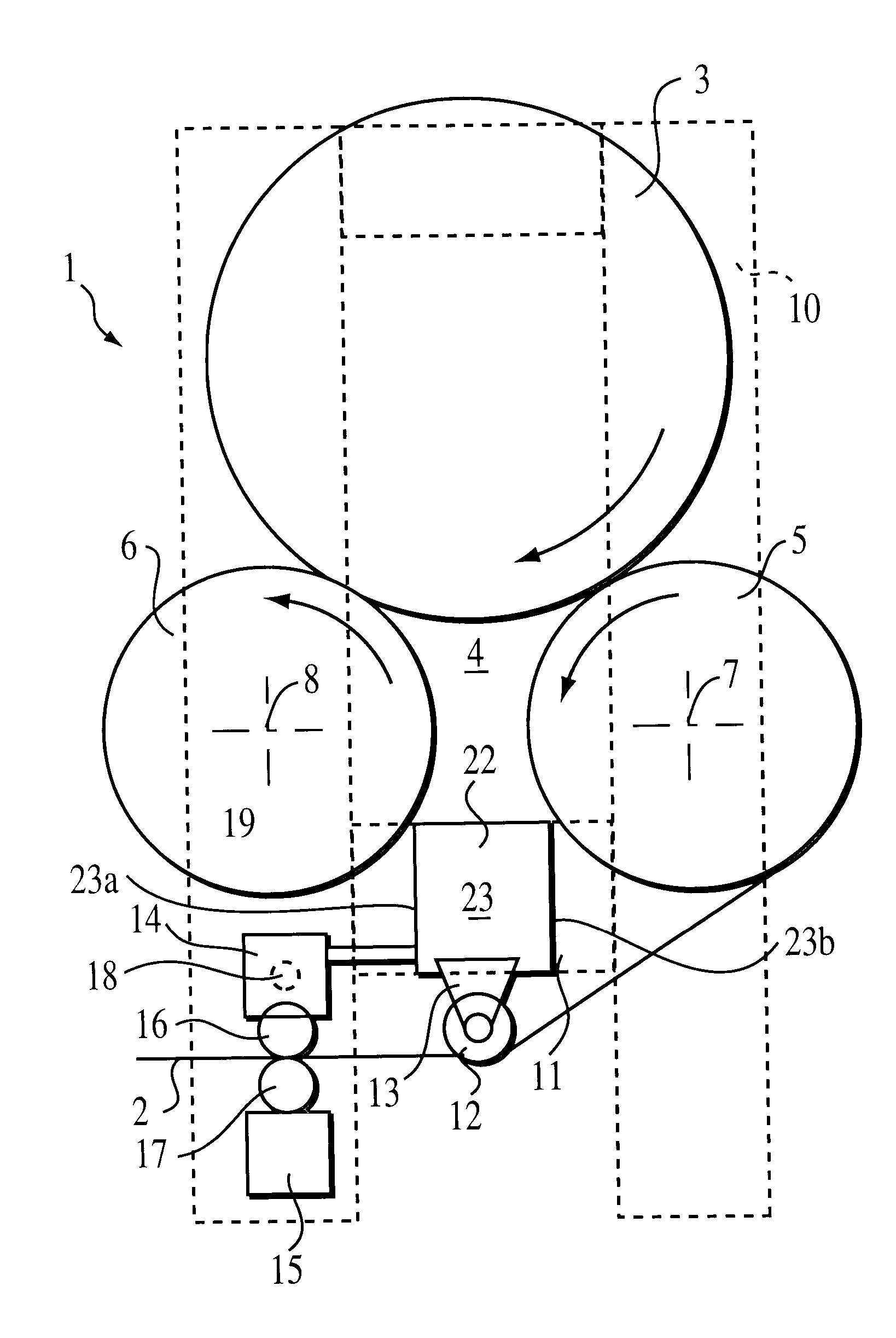
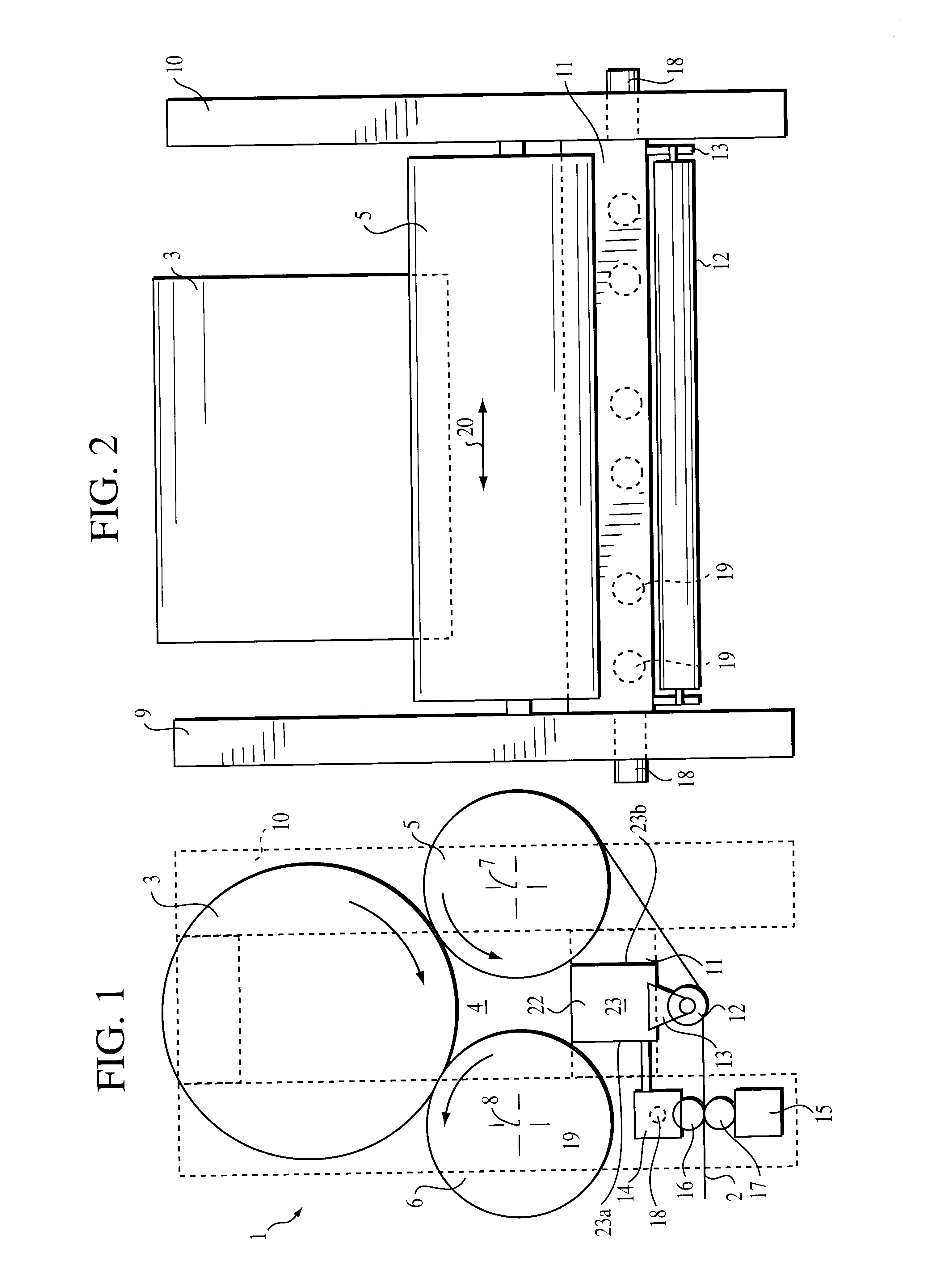
In particular, the invention provides a roll winding device of the type mentioned above by virtue of the fact that the at least one cross bar is embodied as a sealing box, which in turn is disposed beneath a winding bed and which also has a high mechanical stability so that it considerably increases the rigidity of the frame.
In accordance with the invention, the sealing box, unexpectedly, can be utilized for an additional function. Specifically, it can also be used as a cross bar, which connects the two column devices to each other in the immediate vicinity of the carrying rolls. This achieves a stiffening of the machine frame right in the region where it can have the greatest effect. It is unexpected that the sealing box could be used successfully as a structural reinforcing element such as a cross bar in accordance with the present invention, because, for example, as indicated above, conventional wisdom dictates that structural reinforcing members such as cross bars must be spaced away from the carrying rolls a significant distance. Additionally, rather than providing a separate cross bar as a separate structural member, it has been unexpectedly discovered in accordance with the present invention, that the sealing box can be utilized to provide a sufficiently high mechanical stability. With higher air pressures and greater spans, the sealing box has to have a greater stability in order to prevent an outward buckling in the axial center of the winding bed, which could lead to a greater sealing problem, and thus it has been found that the sealing box may be successfully employed as a stiffening or structural element such as a cross bar.
The sealing box advantageously supports a guide roll, and thus, the sealing box accordance with the present invention provides multiple functions. In this manner, other cross bars can be eliminated in order to reduce costs and to save on installation space.
In some embodiments, the invention provides a roll winding device, comprising a winding bed and at least one support device comprising at least one carrying roll. The carrying roll has a first end and a second end and a longitudinal axis and is disposed in the lateral direction with respect to the direction of travel of the web, in a machine frame comprising a column device at each of the two ends of the carrying roll. The column devices are connected to each other in the lateral direction by means of at least one cross bar. At least one cross bar comprises a sealing box that is disposed underneath the winding bed, the sealing box being constructed and arranged so as to have a high mechanical stability so that it considerably increases the rigidity of the frame.
In method aspects, the invention provides a method of increasing the rigidity of a roll winding device, the roll winding device comprising a frame having first and second ends, the frame comprising a first column structure at the first end and a second column structure at the second end;

Problems solved by technology

Vibrations are introduced there, for example, which are caused by imbalances in the carrying rolls that cannot be completely eliminated.
In this position, however, the column devices cannot be connected directly, because the corresponding space is taken up by the carrying rolls.

Method used


Image

  • Roll winding device and method of increasing rigidity of such device
  • Roll winding device and method of increasing rigidity of such device

Examples


Embodiment Construction

The particulars shown herein are by way of example and for purposes of illustrative discussion of the embodiments of the present invention only and are presented in the cause of providing what is believed to be the most useful and readily understood description of the principles and conceptual aspects of the present invention. In this regard, no attempt is made to show structural details of the present invention in more detail than is necessary for the fundamental understanding of the present invention, the description taken with the drawings making apparent to those skilled in the art how the several forms of the present invention may be embodied in practice.

A roll winding device 1 is used to wind a paper web 2 or another material web into a winding roll (reel) 3. The winding roll 3 in this case rests on a winding bed 4, which comprises two carrying rolls 5, 6.

The carrying rolls 5, 6 are disposed in a machine frame with their axes 7, 8 in the lateral direction. At each of the two a...


PUM

PropertyMeasurementUnit
resistance moment Wxaaaaaaaaaa
lengthaaaaaaaaaa
rigidityaaaaaaaaaa

Abstract

Roll winding device, in particular for a reel cutter, with at least one support device, comprising at least one carrying roll disposed with its axis in the lateral direction in a machine frame, which has a column device disposed on each of the two axial ends of the carrying roll, the columns being connected to each other in the lateral direction by means of at least one cross bar. At least one cross bar is embodied as a sealing box which is disposed underneath a winding bed and has a high mechanical stability so that it considerably increases the rigidity of the frame.

Description

The present application claims priority under 35 U.S.C. .sctn. 119 of German Patent Application No. 198 18 944.3, filed on Apr. 28, 1998, the disclosure of which is expressly incorporated by reference herein in its entirety.1. Field of the InventionThe invention relates to a roll winding device, particularly useful in association with a reel cutter, comprising at least one support device comprising at least one carrying roll that is disposed with its axis in the lateral direction in the machine frame, which has a column device on the two axial ends of the carrying roll and these columns are connected to each other in the lateral direction by means of at least one cross bar. The invention also relates to a method of increasing the rigidity of such a roll winding device.Although the description in the present specification is in connection with a roll winding device for winding a paper web, it will be readily understood that the invention and the discussion herein can be applied in th...

Claims


Application Information

Patent Timeline
Patent Type & Authority Patents(United States)
IPC IPC(8): B65H18/14B65H18/20
CPCB65H18/20B65H2301/4148B65H2401/231B65H2402/40B65H2406/13B65H2406/131B65H2408/2321B65H2401/23
Inventor CRAMER, DIRK
Owner VOITH PATENT GMBH
Learn More