Spinal osteosynthesis device

Inactive Publication Date: 2004-03-23
SOFAMOR
View PDF20 Cites 154 Cited by
  • Summary
  • Abstract
  • Description
  • Claims
  • Application Information

AI Technical Summary

Benefits of technology

One object of the invention is to provide a spinal osteosynthesis device so arranged as to

Problems solved by technology

Consequently, if it is desired to increase the spacing between two consecutive anchorage elements, for example in the treatment of spondylolisthesis or for restoring

Method used


Image

  • Spinal osteosynthesis device
  • Spinal osteosynthesis device

Examples


Embodiment Construction

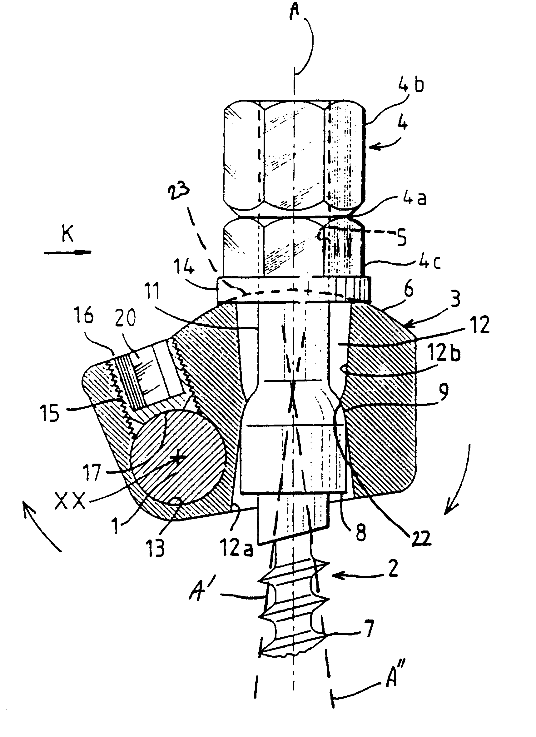
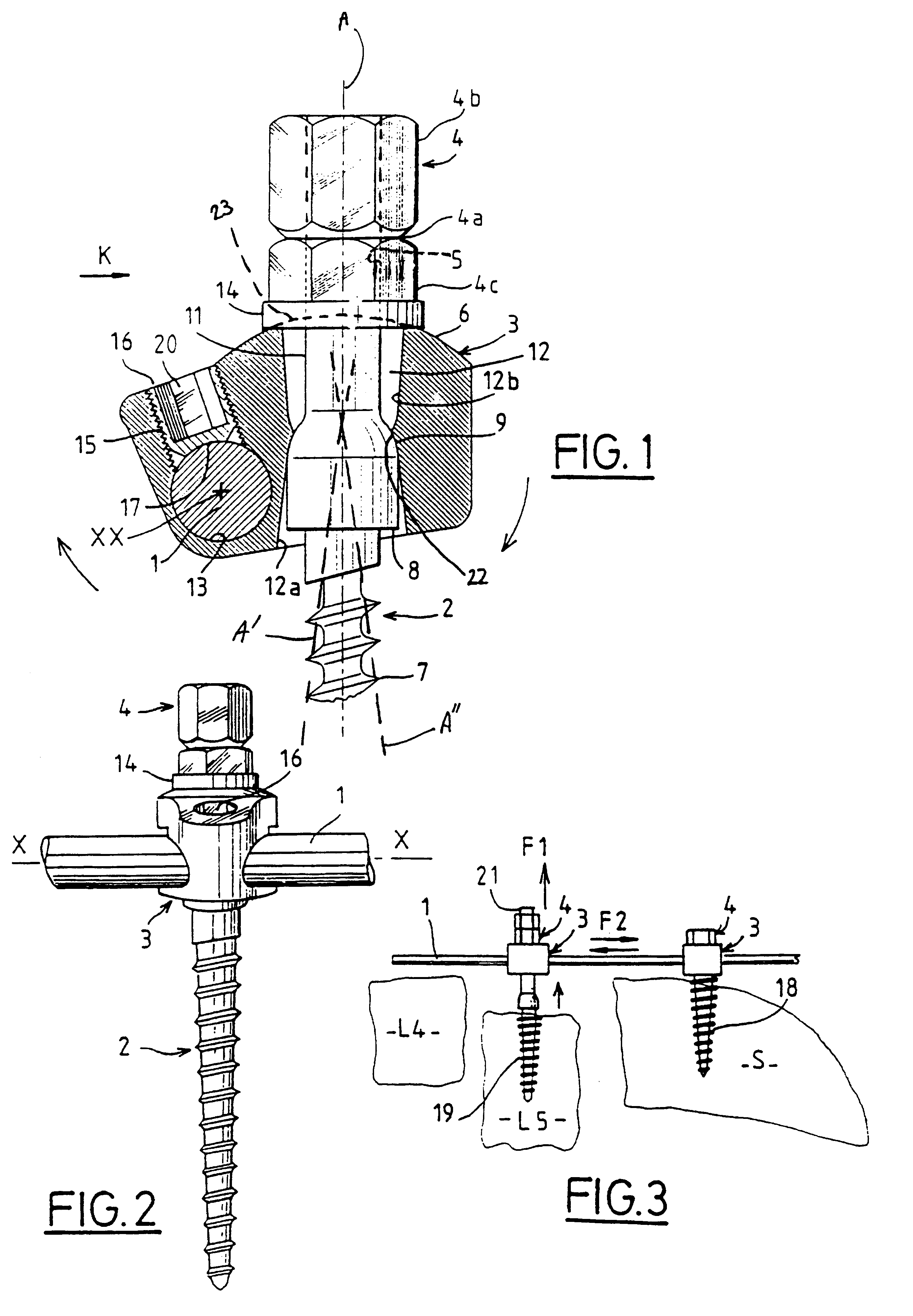
The spinal osteosynthesis device illustrated in FIGS. 1 and 2 comprises a vertebral rod 1, a bone anchorage element 2 constituted in this embodiment by a pedicle screw, and a connector 3 for interconnecting rod 1 and anchorage element 2. This embodiment includes a nut 4 for clamping the assembly of the parts 1, 2, and 3, which is adapted to be screwed on a threaded end part 5 of bone anchorage element 2.

Bone anchorage part 7 is in the illustrated embodiment a screw which is extended by a cylindrical head 8 itself followed by a convex and preferably spherical bearing surface 9 which has the same center of curvature as surface 6 and is connected to end part 5 by a smooth shank 11.

Head 8, bearing surface 9 and shank 11 are disposed in an opening 12 extending throughout connector 3 in a direction substantially perpendicular to the longitudinal axis XX of the rod 1. Rod 1 is itself disposed in a cylindrical channel 13 formed in connector 3 to one side of opening 12. Opening 12 has a firs...


PUM


Abstract

A spinal osteosynthesis device comprising a bone anchorage element, a vertebral rod, a connector for interconnecting the rod and the anchorage element so that the anchorage element is capable of being angularly oriented in a polyaxial manner relative to the rod. A fixation element is provided for fixing the position of the connector in translation and in rotation relative to the rod. A clamp element is provided for clamping the bone anchorage element to the connector in a predetermined angular position independent of the fixation element.

Description

TECHNICAL FIELD BACKGROUNDThe present invention relates to a bone implant apparatus, and more specifically but not exclusively a spinal osteosynthesis device of the type including a bone anchorage element, a vertebral rod, and a connector for interconnecting the rod and the anchorage element such that the anchorage element is capable of being angularly oriented in a polyaxial manner relative to the rod.U.S. Pat. No. 5,486,174 and EP-A-0612507 describe such devices in which the connector is constituted by two jaws which define a lateral recess for the rod and in which conical openings are provided for the passage of the bone anchorage element. The latter comprises a shank having a double screw thread, one end part of which constitutes a bone anchorage screw. The opposite threaded end part projects from the upper jaw to permit the clamping of the assembly of the parts by a nut which comes to bear against the upper jaw.Provided between the two threaded parts of the anchorage element sh...

Claims


Application Information

Patent Timeline
IPC IPC(8): A61B17/70A61B17/58
CPCA61B17/7037A61B17/7041A61B17/7035
Inventor GOURNAY, JOSEGOVERNATORI, SERGE
Owner SOFAMOR
Why Eureka
Try Eureka