Illumination flicker detection apparatus, an illumination flicker compensation apparatus, and an ac line frequency detection apparatus, methods of detecting illumination flicker, compensating illumination flicker, and measuring ac line frequency

a technology of illumination flicker and detection apparatus, which is applied in the direction of color television details, color signal processing circuits, television systems, etc., can solve the problems of flicker and deterioration of the quality of the reproduced imag

Inactive Publication Date: 2004-03-23
PANASONIC CORP
View PDF12 Cites 182 Cited by
  • Summary
  • Abstract
  • Description
  • Claims
  • Application Information

AI Technical Summary

Problems solved by technology

When image is taken by a video camera under illumination by fluorescent lamps, there is a problem of flicker.
However, if the ac line frequency varies around 60 Hz, black stripes move every frame, so that quality of the reproduced image is deteriorated.

Method used


Image

  • Illumination flicker detection apparatus, an illumination flicker compensation apparatus, and an ac line frequency detection apparatus, methods of detecting illumination flicker, compensating illumination flicker, and measuring ac line frequency
  • Illumination flicker detection apparatus, an illumination flicker compensation apparatus, and an ac line frequency detection apparatus, methods of detecting illumination flicker, compensating illumination flicker, and measuring ac line frequency
  • Illumination flicker detection apparatus, an illumination flicker compensation apparatus, and an ac line frequency detection apparatus, methods of detecting illumination flicker, compensating illumination flicker, and measuring ac line frequency

Examples


first embodiment

FIGS. 2A and 2B are illustration of the

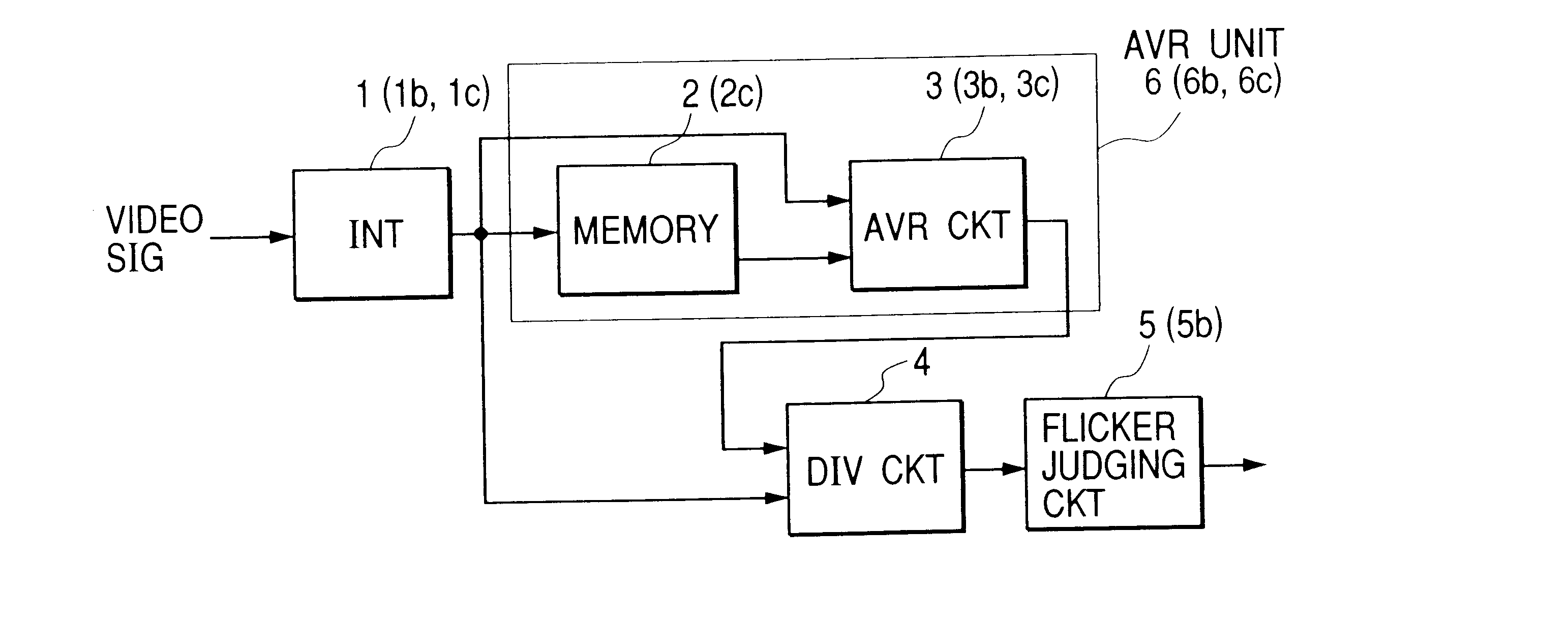
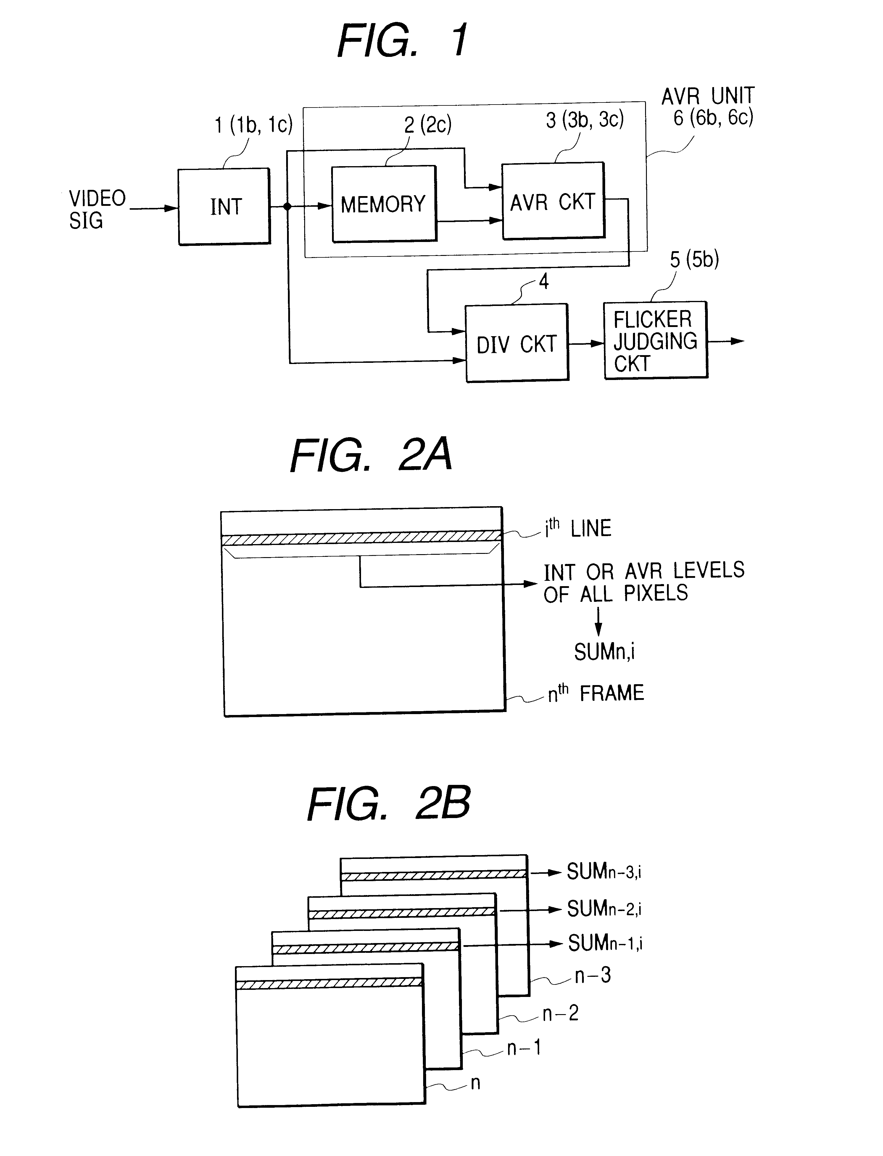
The integration circuit 1 integrates, accumulates, or averages the pixel levels (luminance level) at every horizontal line (unit area). The integrating result of i.sup.th line of n.sup.th frame is represented by SUM.sub.ni as shown in FIG. 2A. If one frame of the video signal includes 480 lines, the integration circuit 1 calculates the integration result SUM.sub.n,1 to SUM.sub.n,480 for i=1 to 480.

The memory 2 successively stores a predetermined number of frames (fields) of the integration result. The averaging circuit 3 effects addition or averaging among SUM.sub.n,i from the integration circuit 1, SUM.sub.n-1,i, SUM.sub.n-2,i, and SUM.sub.n-3,i from the memory 2. FIG. 2B shows the summing or averaging operation from the integration results of the present frame and the previous frames. The memory 2 stores the integration result SUM.sub.n, i and outputs the integration results SUM.sub.n-1, i, SUM.sub.n-2, i, SUM.sub.n-3, i at the i.sup.th line ...

second embodiment

FIG. 5 is an illustration of integration operation according to the

It is assumed that the integrated or averaged values of video levels of all significant pixels on the i.sup.th line, (i+1).sup.th line, and (i+2).sup.th line at n.sup.th frame are represented as SUM.sub.nI and that on the (i+3).sup.th line, (i+4).sup.th line, and (i+5).sup.th line at n.sup.th frame is represented as SUM.sub.nI+1.

This embodiment is effective for video signals obtained from imagers using color filters. FIGS. 6A and 6B show arrangements of color filters for single plate imagers and processing in this embodiment. The arrangement shown in FIG. 6A is for the complementary filter structure and the arrangement shown in FIG. 6B is a portion of Bayer arrangement for primary color filter structure. As shown in FIGS. 6A and 6B, different color filters are arranged and adhered on imagers.

In the complementary color filter type of imager, a first line and a second line are alternately arranged, wherein a cyan filte...

third embodiment

FIG. 7 is an illustration according to the

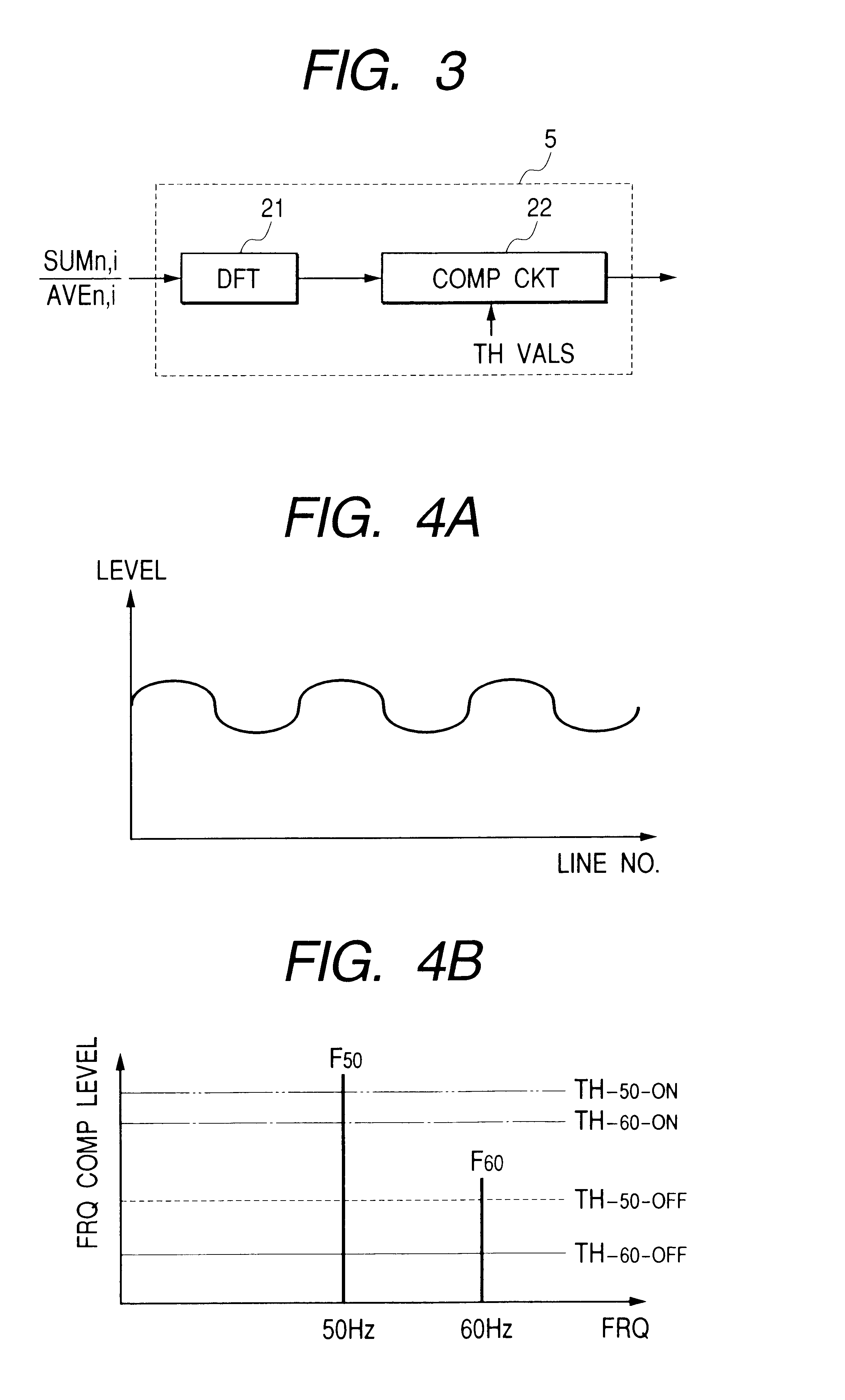
In the case that an image is shot under illumination using the ac line of 50 Hz, there are periodical level variations (3+1 / 3) times a frame as shown in FIG. 7. In the case of 60 Hz, there are four periodical level variations on a frame.

Then, the integrating circuit 1c integrates the video signal level on the horizontal lines (unit area) showing the same phase in the illumination flicker. That is, the integration circuit 1c integrates or averages video levels of pixels on the j.sup.th line, (j+p).sup.th line, and (l+2p).sup.th line. This level is represented as SUM.sub.nj. The averaged value of the video levels of pixels on the j.sup.th (j+1).sup.th line, (j+1+p).sup.th line, and (l+1+2p).sup.th line is represented as SUM.sub.nj+1.

Each of the unit areas includes a plurality of horizontal lines with interval at a frame, which horizontal lines show the same phase in flicker component in said video signal. The number of the horizontal lines in ...


PUM


Abstract

A video signal including illumination flicker component is integrated at each of unit areas (horizontal lines) in a frame (field) of the video signal. The integrated level at each of the unit areas at the frame and the integrated level at the corresponding unit area of an adjacent frame are averaged. Dividing is effected between results of the averaging and integrating every unit area. It is judged whether flicker exists in the video signal by frequency-analyzing results of the dividing result at the unit areas. The unit area may be plural adjacent lines where flickering are negligible. The averaging circuit may be circulation type of or FIR filter. Threshold level for judging the flicker is changed according to a shutter speed control signal. Flicker compensation may be executed by controlling shutter speed or the AGC according to flicker judging result. A still condition at a block in a frame may be detected from the integration result at plural frames. When the block is judged to be still, the flicker is judged. An ac line frequency detection is also disclosed to detect the frequency of the ac line from a video signal generated under illumination including flicker. An imaging circuit may be provided to generate the video signal therein.

Description

1. Field of the InventionThis invention relates to an illumination flicker detection apparatus, an illumination flicker compensation apparatus, and an ac line frequency detection apparatus, methods of detecting illumination flicker, compensating flicker, and measuring ac line frequency.2. Description of the Prior ArtAn illumination flicker detection apparatus for detecting flicker in a video signal which is generated by a video camera under illumination by fluorescent lamps are known. Moreover, a video signal processing apparatus for suppressing the affection by flicker in the video signal is also known.When image is taken by a video camera under illumination by fluorescent lamps, there is a problem of flicker. Illumination level of the fluorescent lamp periodically changes with voltage variation of the ac line. FIGS. 19A to 19D are illustrations of a prior art showing a relation between luminance changes of fluorescent lamps and the image shooting operation. If the cycle of the vol...

Claims


Application Information

Patent Timeline
Patent Type & Authority Patents(United States)
IPC IPC(8): H04N5/235
CPCH04N5/235H04N5/2357H04N23/745H04N23/70
Inventor KASAHARA, MISATABEI, KENJISUBE, MAKOTO
Owner PANASONIC CORP
Why Eureka
Try Eureka