Knit convolute protective sleeve

a protective sleeve and convolute technology, applied in the field of elongated convolute sleeve, can solve the problems of severe vibration, abrasion and physical impact damage, and the extreme heat and cold of the fuel line or hydraulic line,

Inactive Publication Date: 2004-03-30
FEDERAL MOGUL WORLD WIDE LLC
View PDF16 Cites 22 Cited by
  • Summary
  • Abstract
  • Description
  • Claims
  • Application Information

AI Technical Summary

Problems solved by technology

A wiring harness, fuel line or hydraulic line may be subjected to extremes of heat and cold, radio frequency/electromagnetic interference (RFI/EMI), severe vibration, abrasion and physical impact damage when used in the engine

Method used


Image

  • Knit convolute protective sleeve
  • Knit convolute protective sleeve
  • Knit convolute protective sleeve

Examples


Embodiment Construction

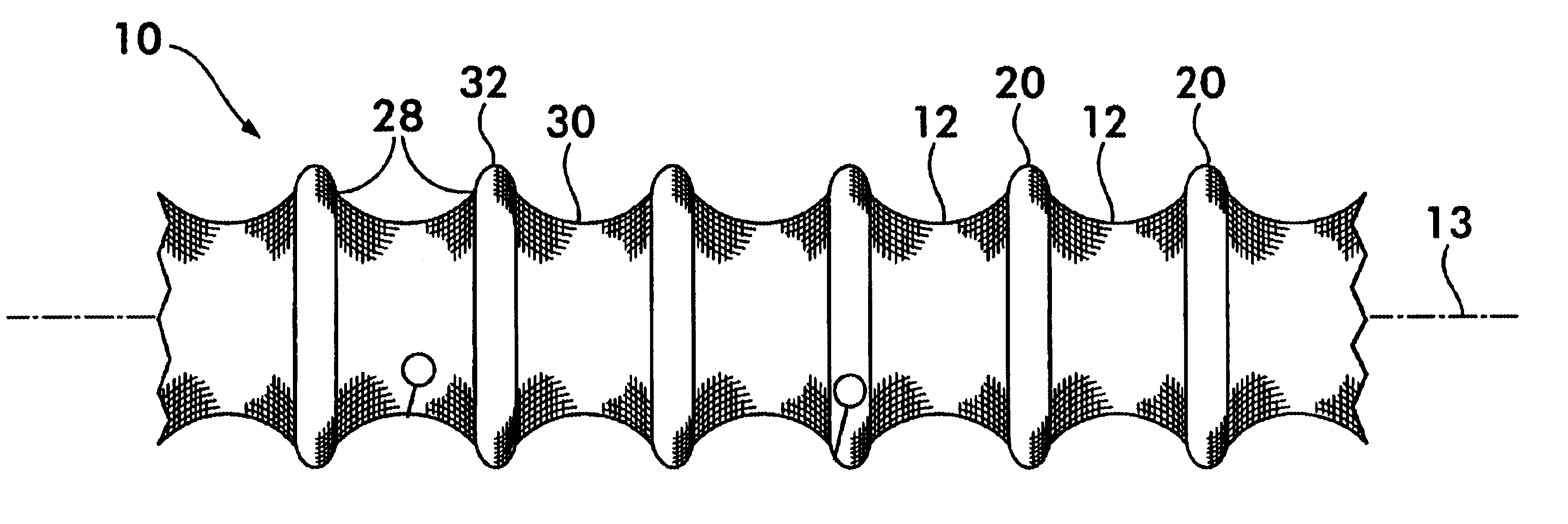
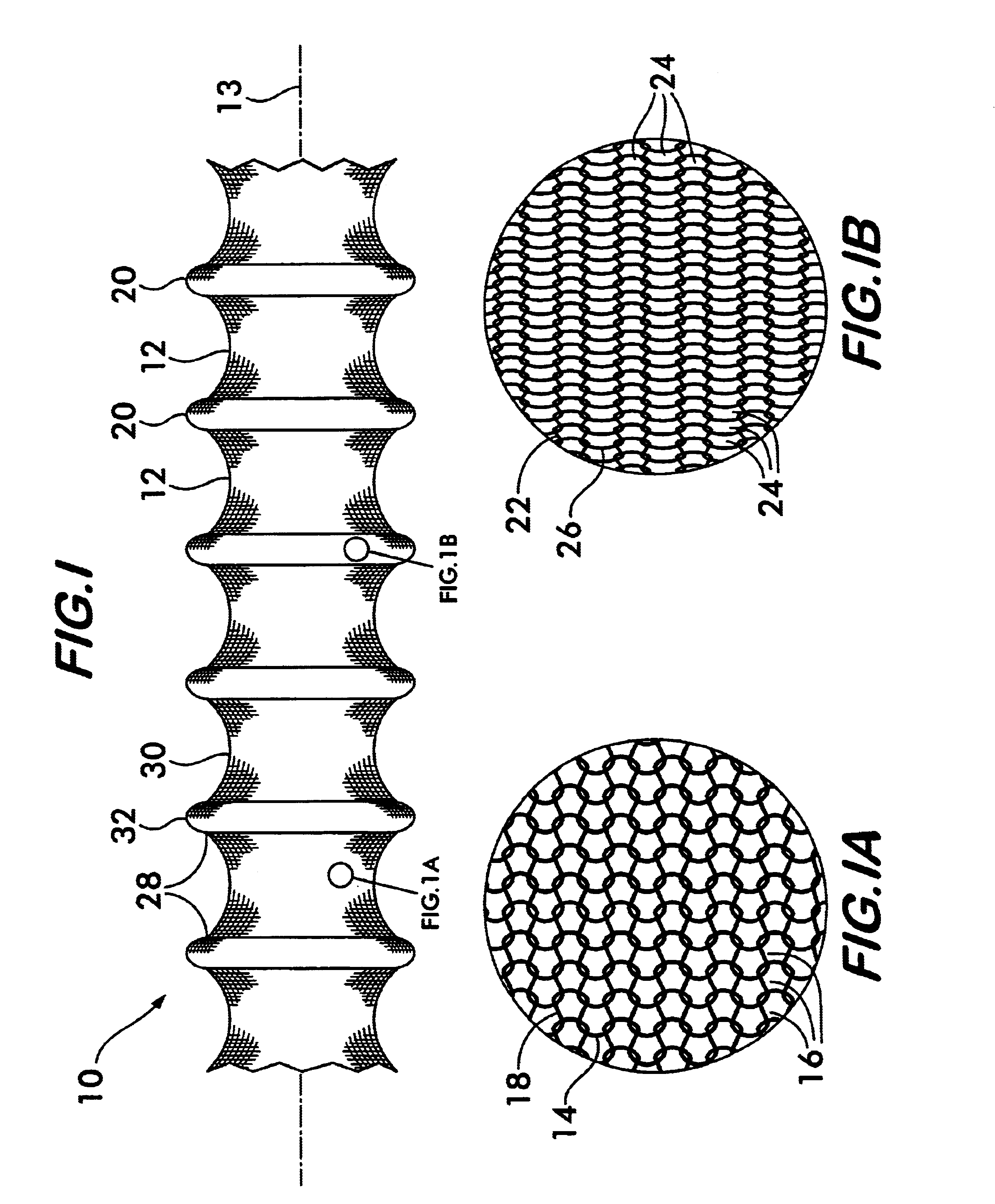
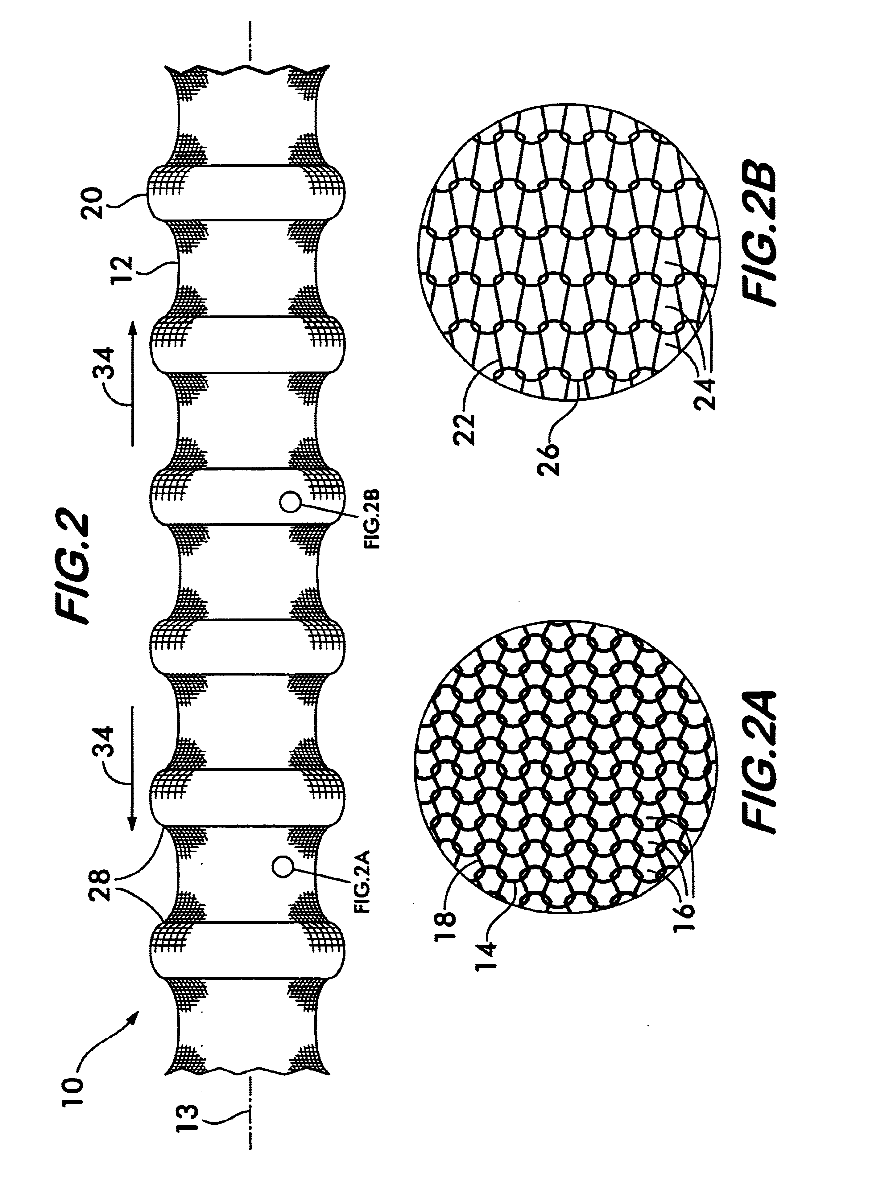
. 1 shows an embodiment of the knitted convolute sleeve 10 according to the invention. Sleeve 10 is formed of a plurality of tubular first segments 12 positioned coaxially in spaced relation along an axis 13. As shown on an enlarged scale in FIG. 1A, first segments 12 are knitted of a plurality of filamentary members 14 forming courses 16 of loops 18 which extend circumferentially around sleeve 10. The sleeve also has a plurality of tubular second segments 20 positioned coaxially along axis 13 in an alternating pattern with segments 12. As shown on an enlarged scale in FIG. 1B, second segments 20 are knitted of a plurality of filamentary members 22 forming courses 24 of loops 26 which extend circumferentially around sleeve 10. The first and second segments are interknitted together end to end in alternating fashion to form the sleeve 10.

Filamentary members 14 comprising first segments 12 are flexible, resilient and have greater stiffness than the filamentary members 22 comprising se...


PUM

PropertyMeasurementUnit
Lengthaaaaaaaaaa
Diameteraaaaaaaaaa
Densityaaaaaaaaaa

Abstract

A knitted convolute protective sleeve is disclosed. The sleeve is knitted from filamentary members to form alternating crests and troughs lengthwise along the sleeve. The crests and troughs may be formed by alternatingly knitting segments from relatively stiff and relatively flexible filamentary members, by interlacing stiffening hoops at spaced intervals lengthwise along a knitted sleeve having a smaller nominal diameter than the hoops, or by varying the knitting parameters, such as loop density and loop length as a function of length along the sleeve.

Description

This invention relates to sleeving for the protection of elongated substrates and especially to convolute sleeving having improved flexibility and radial stiffness.Convolute sleeving is used across a broad range of industrial applications, particularly in electronics, aerospace and automotive applications to provide protection to elongated substrates, such as wiring harnesses and fluid conduits, particularly hydraulic lines and fuel lines, from harsh environments. A wiring harness, fuel line or hydraulic line may be subjected to extremes of heat and cold, radio frequency / electromagnetic interference (RFI / EMI), severe vibration, abrasion and physical impact damage when used in the engine compartment of an aircraft or automobile or on an orbiting satellite.Convolute sleeving is often used to ensheath and protect such elongated substrates from heat, cold, abrasion, vibration and impact damage as well as to provide acoustical damping or shield electrical conductors from RFI / EMI. Because...

Claims


Application Information

Patent Timeline
IPC IPC(8): F16L57/06F16L57/00F16L57/04F16L59/02B32B23/02D04B1/22F16L1/00F16L11/00H02G3/04
CPCF16L57/04F16L57/06F16L59/021D04B1/225D10B2505/12H02G3/0481D07B2205/3025D07B2201/20907D04B1/123D10B2401/062D10B2403/0333D07B2801/22F16L57/00
Inventor AKERS, JESSICA L.MAIDEN, JANICE R.WINTERS, DANNY E.
Owner FEDERAL MOGUL WORLD WIDE LLC
Why Eureka
Try Eureka