Slot antenna
a slot antenna and antenna technology, applied in the field of slot antennas, can solve the problems of difficulty in covering the entire aforementioned wide frequency band, difficulty in realizing an antenna which covers, and the problem of conventional slot antennas in terms of wideband-ness
- Summary
- Abstract
- Description
- Claims
- Application Information
AI Technical Summary
Benefits of technology
Problems solved by technology
Method used
Image
Examples
embodiments
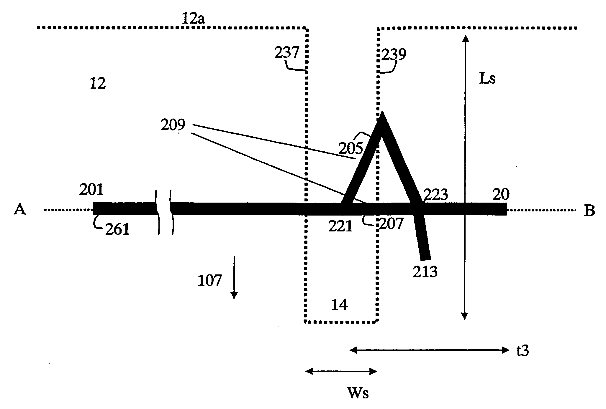
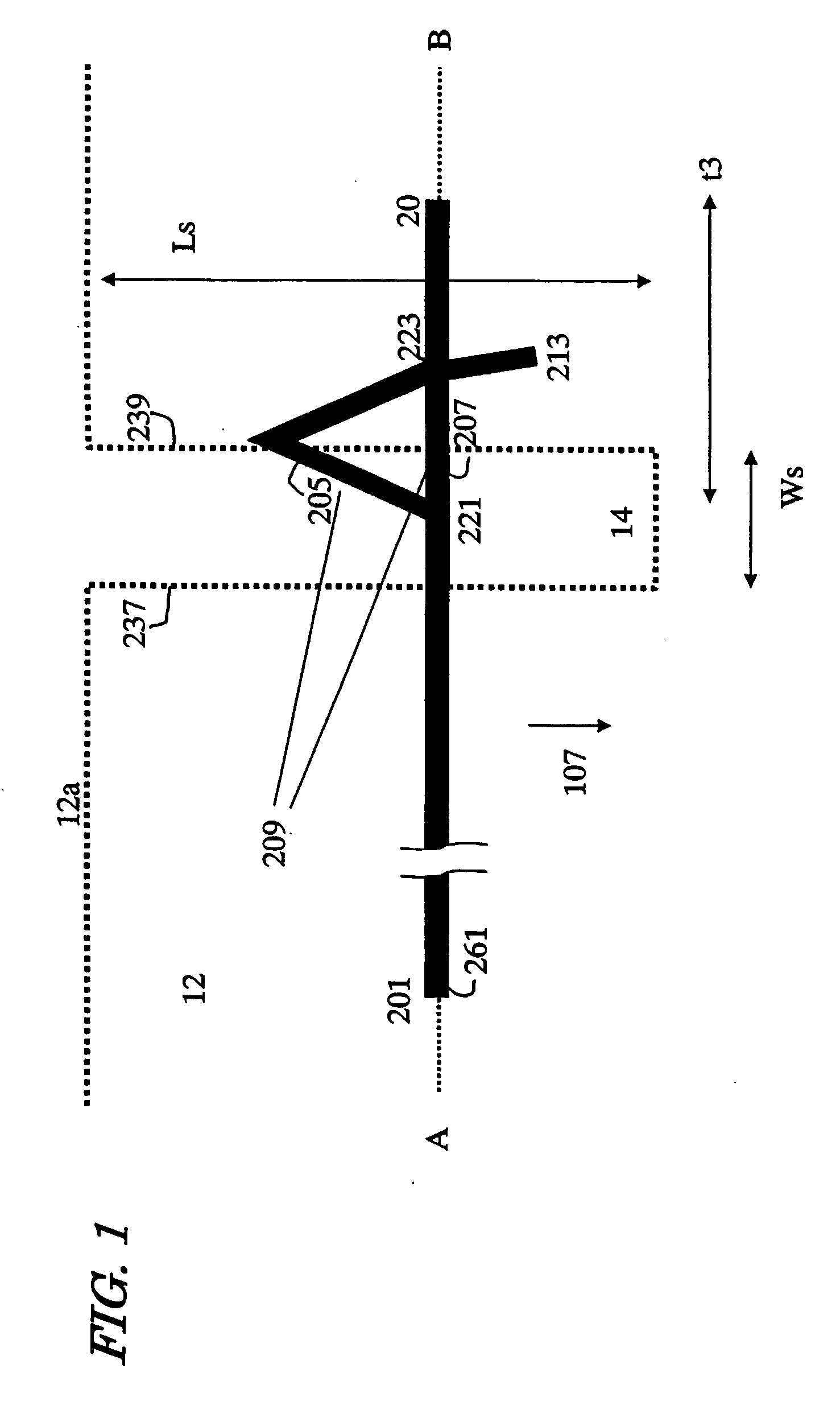
[0060] First, FIG. 1 is referred to. FIG. 1 is an upper schematic see-through view showing the structure of a slot antenna according to the present embodiment.
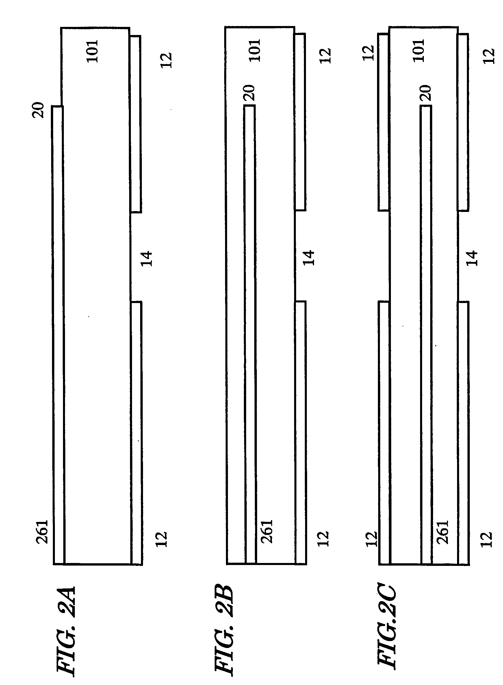
[0061] The slot antenna of the present embodiment includes a dielectric substrate 101 (FIG. 2), and a ground conductor 12 provided on the rear face of the dielectric substrate 101, the ground conductor 12 having a finite area. The ground conductor 12 has a slot 14, which is formed by recessing a side edge 12a of the ground conductor 12 in an inward direction 107. One end of the slot 14 is opened at the side edge 12a of the ground conductor 12, this end functioning as an “open-end point”. Assuming that the slot 14 has a slot width Ws which is negligible relative to the slot length Ls, the slot length Ls is prescribed equal to a ¼ effective wavelength near the center frequency f0 of the operating band. When this assumption is not true, a slot length which takes th e slot width into consideration (Ls×2+Ws) may be prescribed equa...
example
[0104] A slot antenna (Comparative Example 1) as shown in an upper schematic see-through view of FIG. 13 and a slot antenna (Example 1a) as shown in an upper schematic see-through view of FIG. 14 were produced. As a dielectric substrate 101, an FR4 substrate whose overall width was 500 microns and each of whose sides measured 60 mm (a=b=60 mm) was used. On the front face and the rear face of the substrate, a signal conductor pattern and a ground conductor pattern each having a thickness 20 microns were formed, respectively, by using a copper line. Each wiring pattern was formed by removing some regions of the metal layer through wet etching, and gold plating was provided on the surface to a thickness of 5 microns. An outer edge 12a of the ground conductor 12 remained inside the dielectric substrate 101, by no less than 100 microns, even at the closest points to the end faces of the dielectric substrate 101. In the figure, the ground conductor pattern is shown by a dotted line.
[0105...
PUM
 Abstract
Description
Claims
Application Information
 - R&D
- Intellectual Property
- Life Sciences
- Materials
- Tech Scout
- Unparalleled Data Quality
- Higher Quality Content
- 60% Fewer Hallucinations
Browse by: Latest US Patents, China's latest patents, Technical Efficacy Thesaurus, Application Domain, Technology Topic, Popular Technical Reports.
© 2025 PatSnap. All rights reserved.Legal|Privacy policy|Modern Slavery Act Transparency Statement|Sitemap|About US| Contact US: help@patsnap.com


