
Method of providing a remote power feed to a terminal in a local area network, and corresponding remote power feed unit, concentrator, repeator, and terminal

a technology of local area network and remote power feed, which is applied in the direction of liquid/fluent solid measurement, data switching details, instruments, etc., can solve the problems of affecting the free movement of people, affecting the safety of users, so as to prevent all damage risks

Inactive Publication Date: 2004-03-30
ALCATEL LUCENT SAS
View PDF8 Cites 89 Cited by
  • Summary
  • Abstract
  • Description
  • Claims
  • Application Information

AI Technical Summary

Benefits of technology

The invention therefore aims to solve this problem by proposing a method of providing a remote power feed to a terminal in a data processing local area network and systems for implementing the method which prevent all risk of damage if a terminal is plugged in which is not one of the terminals adapted to receive a remote power feed via the network.
The resulting concentrator can be inserted into a line without compromising the advantages for that line of the remote power feed, because it can itself be detected as adapted to receive a remote power feed and therefore receive a remote power feed.

Problems solved by technology

This solution makes installation of the local area network more difficult:
Using two cables causes problems of congestion which can additionally impede the free movement of persons.
It creates electrical hazards.
In the case of a telephone, a local connection to the mains electrical power supply has the additional drawback that the telephone is out of service in the event of a mains power outage, in particular in the event of a fire or natural disaster.
In both cases, providing a remote power feed to the terminal via the data processing local area network has the disadvantage that the remote power feed unit supplies power to a terminal "blind".
There is a risk of damaging the electrical circuits of that terminal.

Method used


Image

  • Method of providing a remote power feed to a terminal in a local area network, and corresponding remote power feed unit, concentrator, repeator, and terminal
  • Method of providing a remote power feed to a terminal in a local area network, and corresponding remote power feed unit, concentrator, repeator, and terminal
  • Method of providing a remote power feed to a terminal in a local area network, and corresponding remote power feed unit, concentrator, repeator, and terminal

Examples


Embodiment Construction

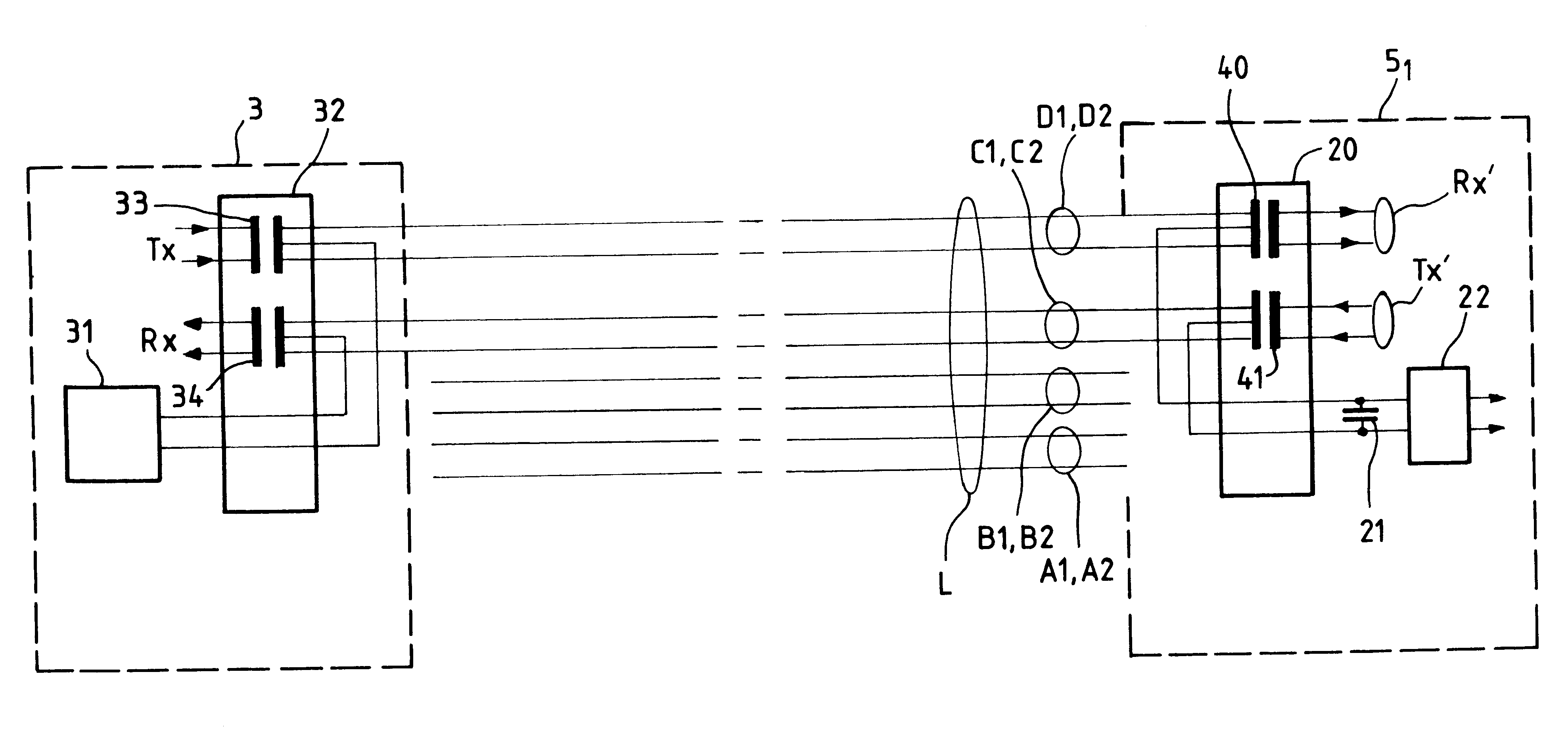
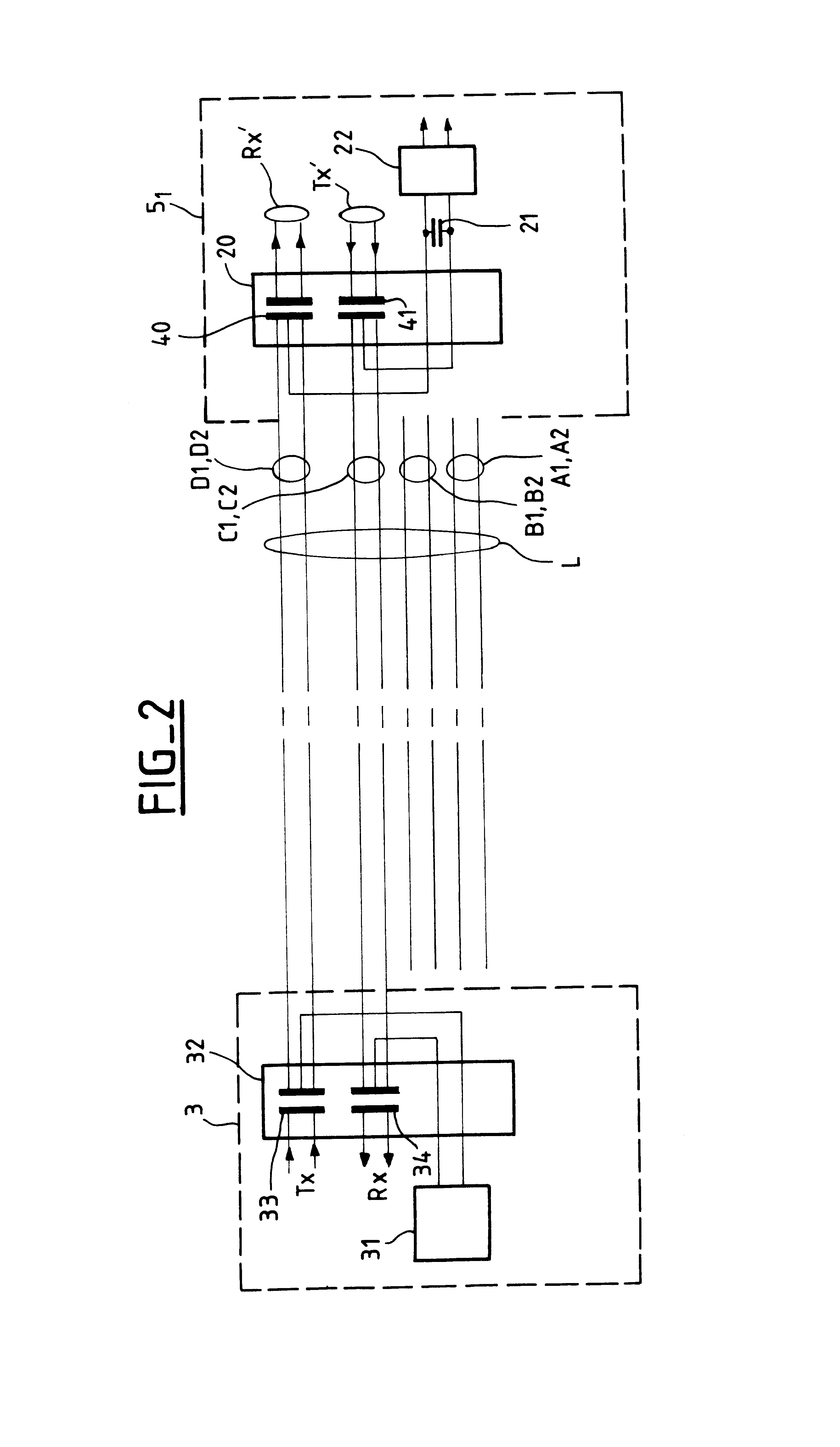
FIG. 2 is a block diagram of a first embodiment of a remote power feed unit located in a concentrator 3 and a first embodiment of a terminal 5.sub.1 adapted to receive a remote power feed, where the remote power feed is provided via a common mode phantom circuit on pairs for sending and receiving data. The line L3 includes four pairs:

pairs A1, A2 are not used,

pairs B1, B2 are not used,

pairs C1, C2 are used to send data to the network, in differential mode, and

pairs D1, D2 are used to send data to the terminal, in differential mode.

The pairs C1, C2 and D1, D2 are also used in common mode to provide a remote power feed to the terminal 5.sub.1 via a phantom circuit.

The concentrator 3 includes a remote power feed unit 31 and a combiner 32. The unit 31 is adapted to detect the presence of a terminal adapted to receive a remote power feed. The combiner 32 includes two transformers 33 and 34 respectively transmitting a signal Tx to be sent to a terminal and a signal Rx received from a term...


PUM


Abstract

A method for sending a remote power feed to a terminal in a local area network.A repeater of the local area network produces a detection signal in a line to which a remote terminal is connected, and the signal has an energy level that will not damage the terminal.The presence of a remote terminal adapted to receive a remote power feed via the repeater is detected by detecting the presence of a predetermined impedance in the terminal, andpower is supplied to the terminal via the repeater in response to detection of the presence of the terminal.

Description

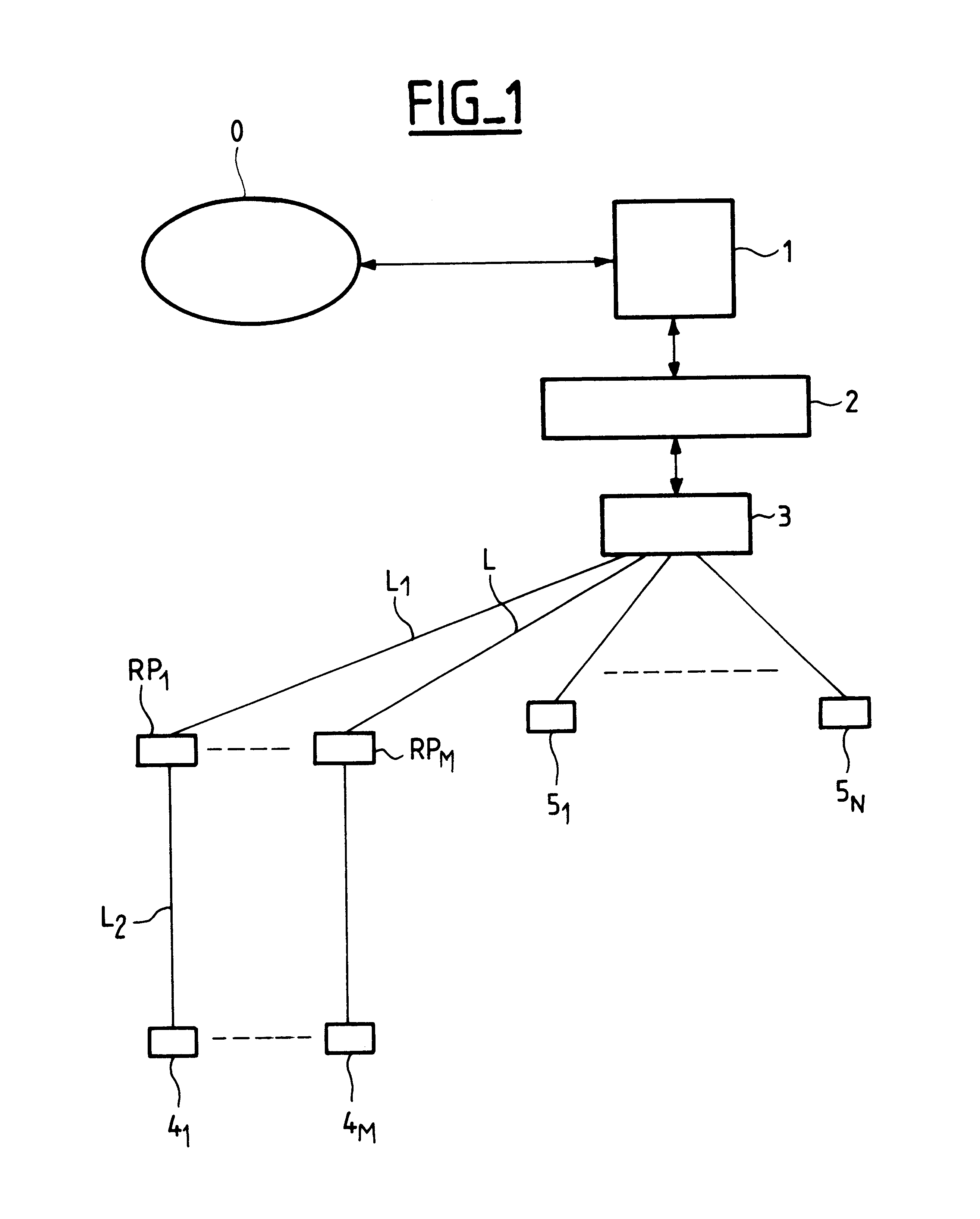
The present invention relates generally to a data processing local area network, for example an Ethernet network. To be more precise, the invention relates to a method of providing a remote power feed to a terminal in a data processing local area network and also to a remote power feed unit, a concentrator, a repeater (also known as a hub), and a terminal adapted to implement the method.FIG. 1 is a diagram showing, by way of illustrative and non-limiting example only, an Ethernet data processing local area network which includes a local area network server 1, a switch 2, a repeater 3 and N terminals 4.sub.1 to 4.sub.N which include telephones operating in Voice over IP (VoIP) mode. The server 1 is connected to the Internet 0 and receives packets complying with the Internet protocol (TCP / IP). The packets of a given call are routed via the switch 2 and the repeater 3 to a terminal such as the telephone 4.sub.1 which is connected to the repeater by a 8-wire line L terminated with RJ45 ...

Claims


Application Information

Patent Timeline
Patent Type & Authority Patents(United States)
IPC IPC(8): H04L12/10H04L12/44
CPCH04L12/10H04L12/44
Inventor VERGNAUD, GERARDATTIMONT, LUCBODIN, JANNICKGASS, RAYMONDLAVILLE, JEAN-CLAUDE
Owner ALCATEL LUCENT SAS
Learn More