
Multicommodity flow method for designing traffic distribution on a multiple-service packetized network

a traffic flow and packetized network technology, applied in the field of multicommo, can solve the problems of not always desirable to make available every call, add an unacceptable cumulative delay, and deem the quality of the call unacceptabl

Inactive Publication Date: 2004-04-13
WSOU INVESTMENTS LLC +1
View PDF9 Cites 54 Cited by
  • Summary
  • Abstract
  • Description
  • Claims
  • Application Information

AI Technical Summary

Problems solved by technology

If there are significant absolute or relative delays, or if the packets arrive out of order, the quality of the call may be deemed unacceptable.
However, it is not always desirable to make available every potential route for a given source-destination pair.
For example, some routes may pass through an excessive number of links (i.e., they have many "hops"), which add an unacceptable cumulative delay.
The problem is compounded by the fact that each link has a limited amount of bandwidth.
The result may be to force some of that traffic onto undesirably long routes as well.
Traffic engineering problems are further complicated when the network is required to carry more than one class of service.
However, they may involve other performance parameters.
It often happens that in order to satisfy QoS requirements, the pertinent traffic must be limited to certain sets of admissible routes.
Any delays which the customer perceives as disrupting the smooth flow of received data will generally be unacceptable.
In particular, premium data traffic might have critical limitations on the call-loss ratio and packet-loss ratio.
Therefore, the network service provider is not expected to guarantee any particular limits on the maximum delay.
However, it is difficult to design a network that will honor such guarantees without blocking an undue amount of traffic.
If these links are necessary for the routing of facsimile transmissions, the result will be a busy signal whenever an attempt is made to send a facsimile.
(A joint routing problem is one that jointly treats all pertinent source-destination pairs.)
Generally, as the size and complexity of networks increases, the time required to solve traffic engineering problems also increases.
Even with the help of tools such as TALISMAN, this is not always feasible for networks that are large or complex.
However, the link-based formulation alone does not lead to a complete solution.
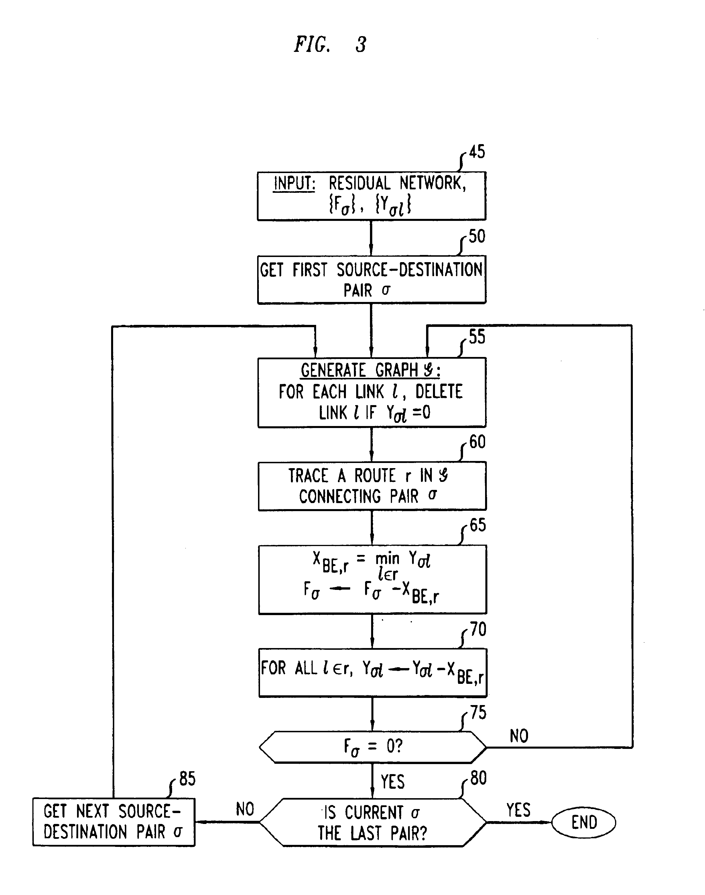
In a given service class, it leads to a link-by-link allocation of bandwidth associated with respective source-destination pairs, but it does not provide an allocation by service route.

Method used


Image

  • Multicommodity flow method for designing traffic distribution on a multiple-service packetized network
  • Multicommodity flow method for designing traffic distribution on a multiple-service packetized network
  • Multicommodity flow method for designing traffic distribution on a multiple-service packetized network

Examples


Embodiment Construction

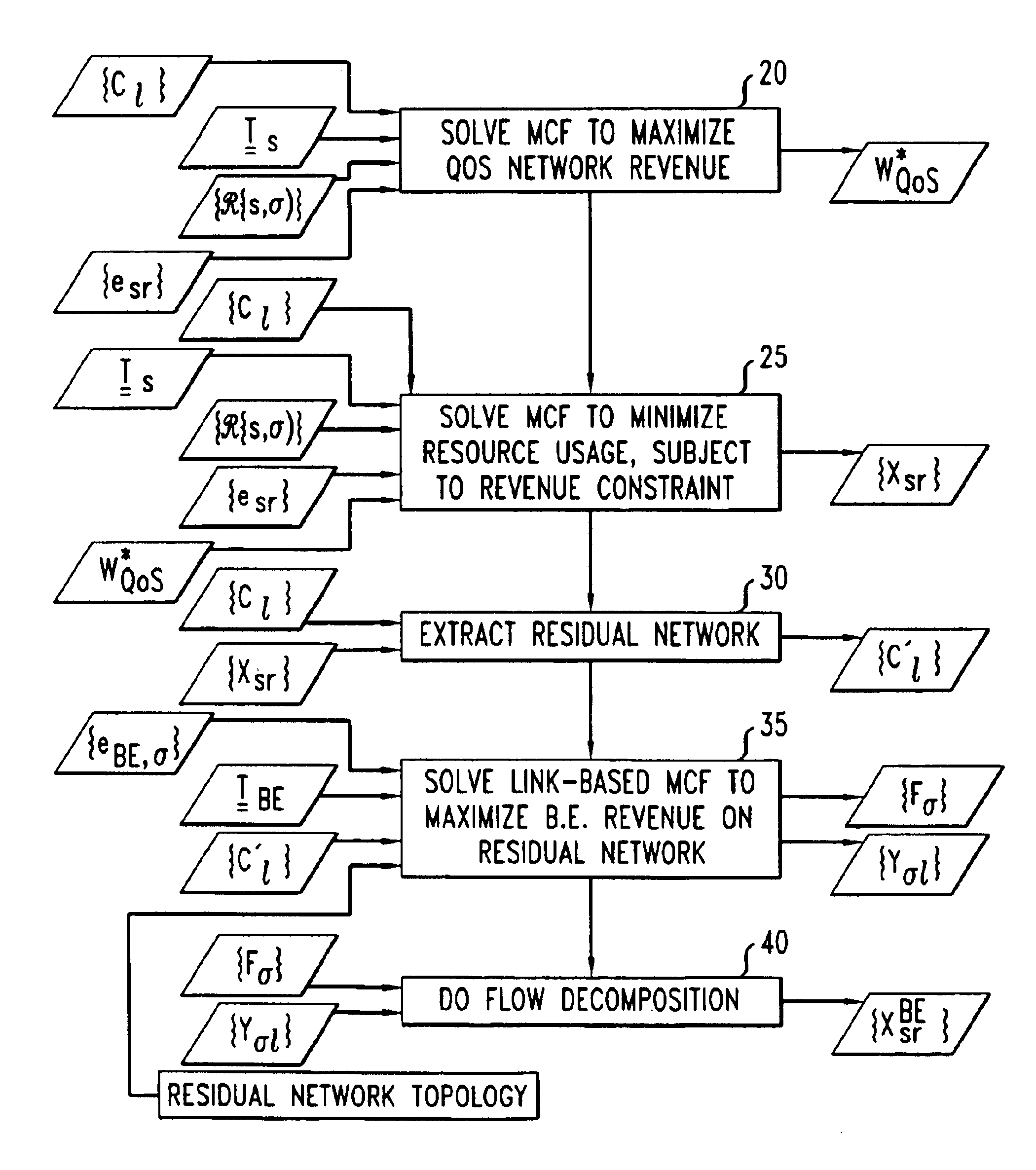
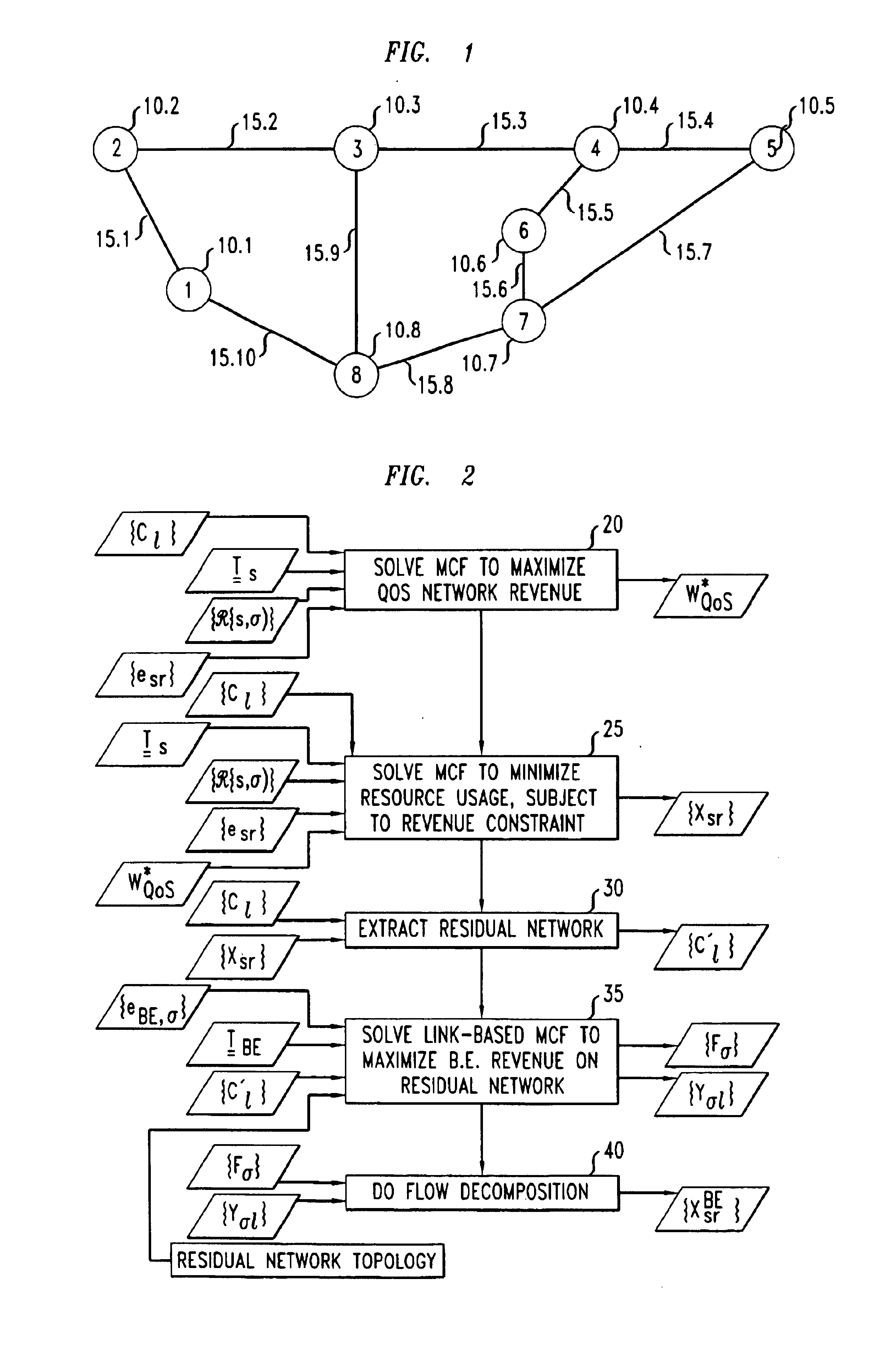
We performed theoretical analyses based on the network of FIG. 1. Each of links 15.1-15.10 is actually a pair of directed links, one in each direction. Each directed link has a bandwidth of 155 Mbps, referred to here as one OC3 unit, except that links 15.3 and 15.8 have capacities, in each direction, of two OC3 units. The service classes are voice (class 1), video (class 2), premium data (class 3), and best effort (class 4). The route sets for classes 1 and 2 are limited to minimum-hop routes. The route set for class 3 is limited to routes of 4 hops or less. The route set for the best effort class is unrestricted. The demand matrices for the four service classes are obtained by multiplying the matrix of Table 1 by 0.4, 0.1, 0.25, and 0.25, respectively. The total demands for the four services classes are 563.5, 140.9, 352.2, and 352.2, respectively.

The procedures of FIG. 2, blocks 20 and 25 were carried out. In the resulting solution, all bandwidth demands were carried. Then, the fu...


PUM


Abstract

A method is described for solving traffic engineering problems in a network. In one aspect, the invention is used in a network that has at least one QoS service class and at least one class of service that is not a QoS class. Bandwidth is allocated to service routes in the QoS service class so as to optimize a figure of merit such as network revenue. Then a new allocation is made so as to minimize network usage without departing too far from the optimal value of the figure of merit. A residual network consists of that bandwidth that remains unallocated, on each link of the network. Bandwidth for non-QoS traffic is allocated to routes on the residual network. In a second aspect, the invention involves the use of optimization techniques to allocate bandwidth among service routes in one or more service classes in response to a set of demands in each class. The demands are calculated so as to take into account an effective bandwidth associated with the pertinent class, and so as to make allowance for the stochastic behavior of the traffic demands that occur in practice.

Description

This invention relates to methods for distributing traffic among routes in packetized communication networks.ART BACKGROUNDCommunication networks transport information between terminal communication devices such as computer terminals, telephones, facsimile machines, and computer file servers. A typical network includes switching nodes such as nodes 10.1-10.8 of FIG. 1, interconnected by links, such as links 15.1-15.10 of the figure. Generally, each terminal device (not shown) is associated with one of the nodes.In many modern networks, the information to be transported from a source node to a destination node is divided into packets or cells. In accordance, for example, with Asynchronous Transfer Mode protocols (ATM) or Internet Protocol (IP), these, e.g., packets stream independently through the network from the source node to the destination node. At each node encountered along the way, a packet is directed into one link or another according to header information borne by that pac...

Claims


Application Information

Patent Timeline
IPC IPC(8): H04Q11/04H04L12/56
CPCH04L49/205H04L49/25H04Q11/0478H04L2012/562H04L2012/5621H04L2012/5623H04L2012/5632H04L2012/5638H04L2012/5684
Inventor MITRA, DEBASISRAMAKRISHNAN, KAJAMALAI GOPALASWAMY
Owner WSOU INVESTMENTS LLC
Learn More