Pressure dome for connecting a transducer with a sealed fluid system

a technology of fluid system and transducer, which is applied in the direction of measurement devices, instruments, other medical devices, etc., can solve the problems of affecting the operation of the monitoring s

Inactive Publication Date: 2004-04-27
MANFRED ADOLFS +1
View PDF7 Cites 143 Cited by
  • Summary
  • Abstract
  • Description
  • Claims
  • Application Information

AI Technical Summary

Benefits of technology

This design, according to the invention, of a connecting element of the type mentioned at the beginning practically rules out the possibility of air bubbles remaining in the measuring chamber, even without for example knocking against the connecting element during filling with infusion solution. The filling without any air bubbles is achieved because the filling takes place from the infusion side to the catheter side in such a way that the long paths at the edge of the measuring chamber fill more quickly as a result of greater heights than the short path in the center. Furthermore, vortexing of the flow and the formation of gas-filled cavities are avoided on account of the surface tension of the fluid. In a way corresponding to this special shaping, the liquid flows meet when they emerge from the measuring chamber. With the previously customary dome-shaped shaping of the measuring chamber, air bubbles can remain in the sides, because the liquid flow blocks the simple escape of the air bubbles on the straight short path to the outlet.
A particularly good compromise between material expenditure and ease of handling is obtained if the grips and retaining elements are dimensioned such that, when the grips are actuated, a ratio of approximately 2:1 to 3:1 between the path of the free ends of the grips and the path of the retaining elements is obtained.

Problems solved by technology

A special problem is that of venting the parts of the monitoring set in connection with the blood system.
The problems involved in venting such systems are generally known to the users.
However, they have the disadvantage that the valuable electronics are integrated in the disposable article and therefore are thrown away each time the monitoring set is changed and have to be disposed of along with it.
This entails not only the disadvantage that the still serviceable electronics are replaced with every change, accompanied by corresponding costs, but also that the presence of electronic components requires additional special, and consequently cost-intensive, treatment as electronic scrap during disposable.
When mounting on the second transducer, the presence of the structure mounted on the first transducer was already a hindrance.
Mounting a second dome onto the second transducer was not possible without removing the transducer from a common retaining plate.
This complicated handling is not only troublesome, it also represents an absolute obstacle to designing retaining plates with permanently fitted transducers and rear-side cabling.
However, it practically rules out a combination with transducers fastened in retaining plates.

Method used


Image

  • Pressure dome for connecting a transducer with a sealed fluid system
  • Pressure dome for connecting a transducer with a sealed fluid system
  • Pressure dome for connecting a transducer with a sealed fluid system

Examples


Embodiment Construction

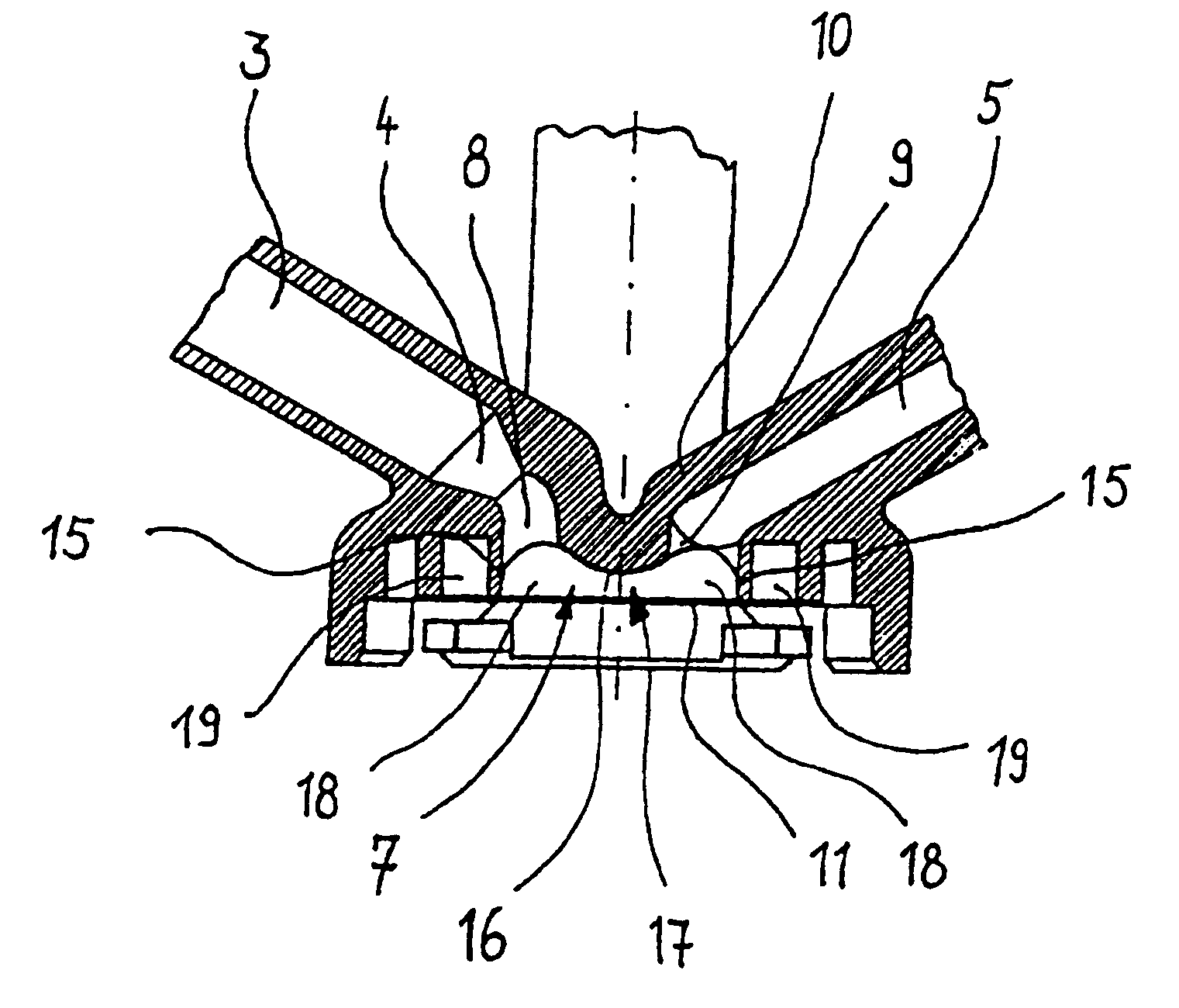
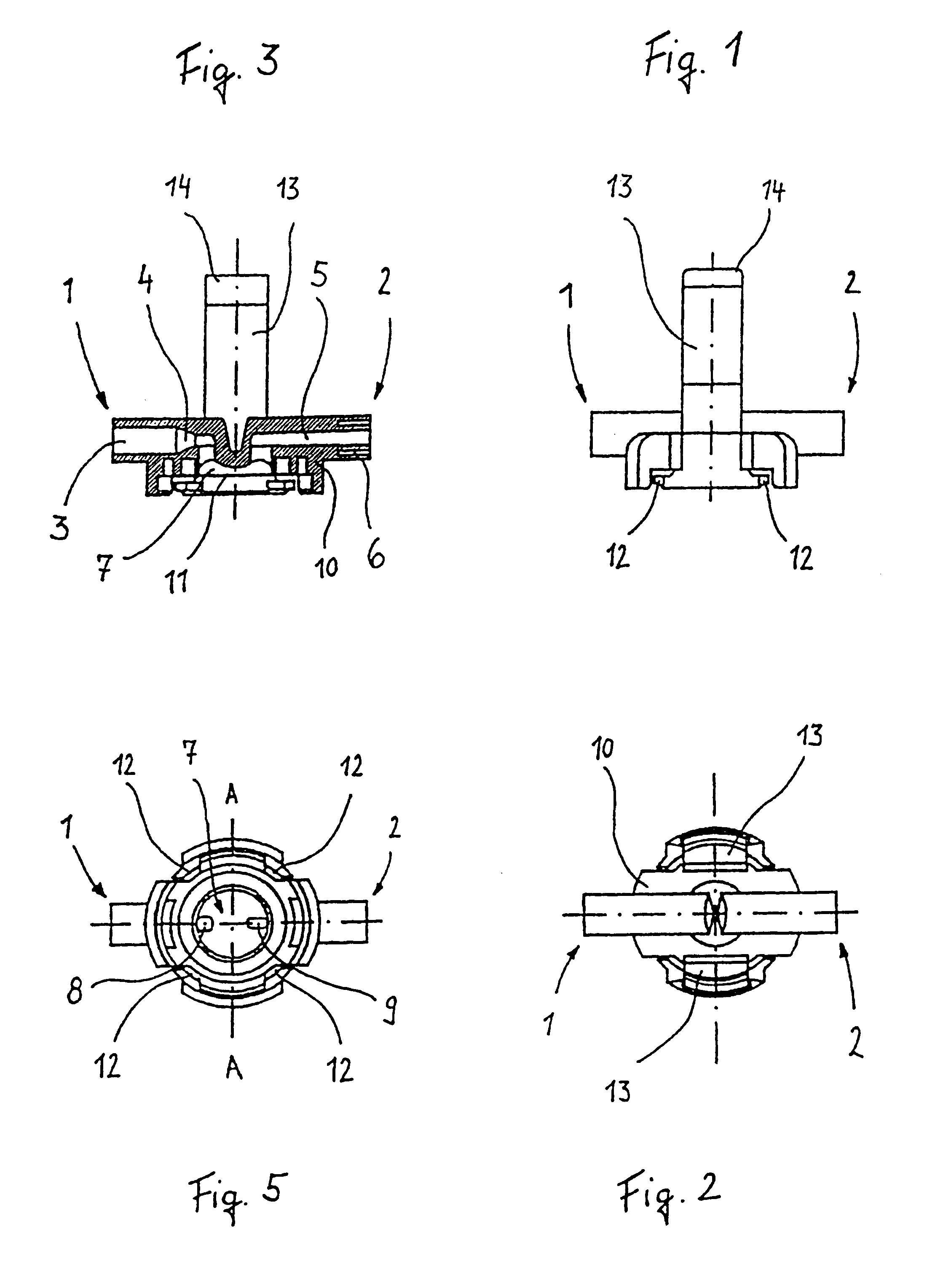
The connecting element represented in FIG. 1 for connecting a transducer to a sealed fluid system has a connection 1 for the connection to an infusion apparatus and a connection 2 for the connection to a patient, for example via a cemented-in three-way cock. The connection 1 for the connection to an infusion apparatus has an inlet channel 3, preferably with a conical packing seat 4. The connection 2 for the connection to a patient contains an outlet channel 5 with a cementing-in groove 6 surrounding the latter (FIG. 3). The dimensioning of the connections 1 and 2 preferably conforms to DIN 13090.

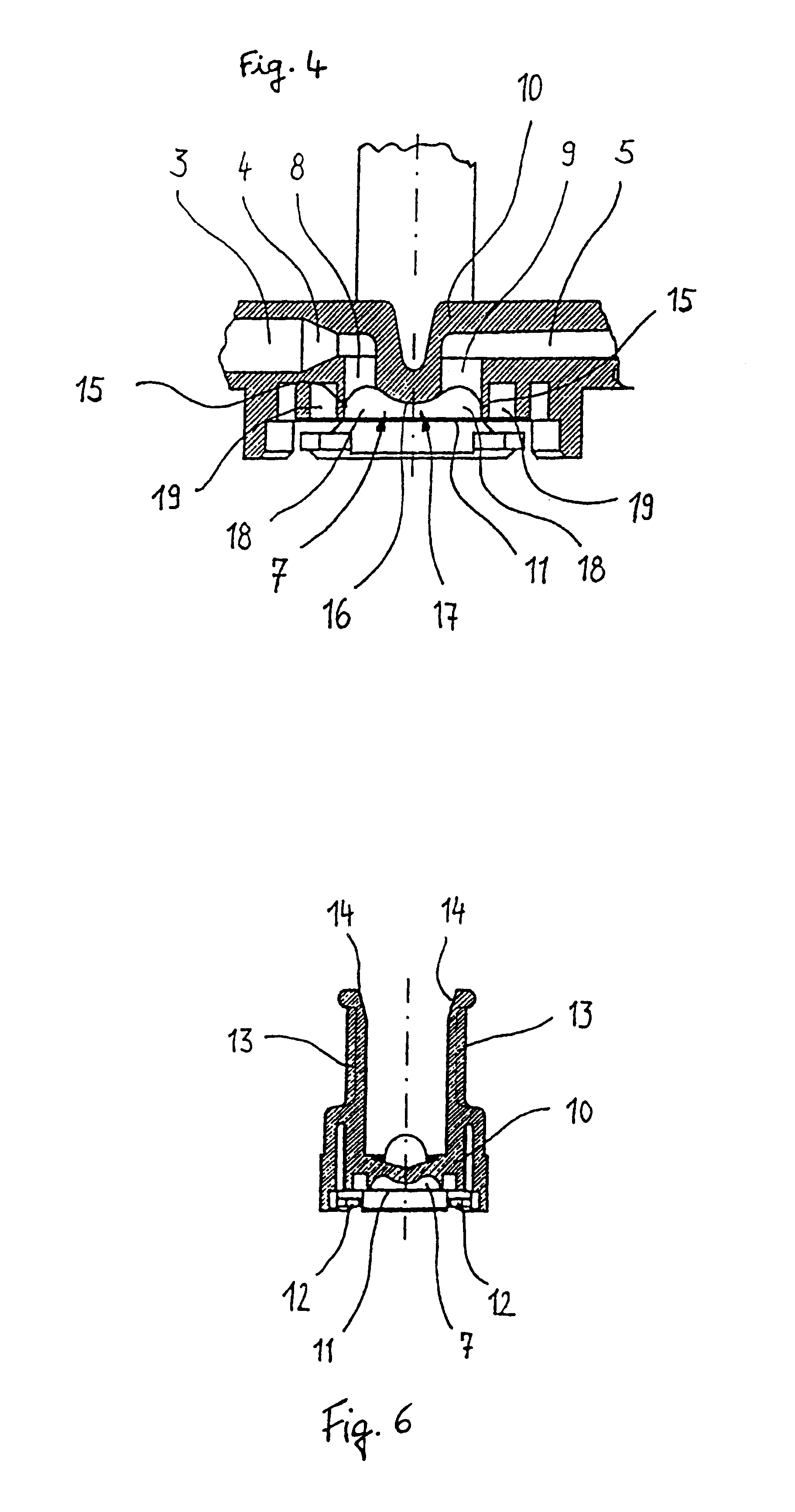
Connected to the inlet channel 3 and the outlet channel 5 via an inlet opening 8 and an outlet opening 9 is a measuring chamber 7 (FIG. 4), so that a flow path from the inlet channel 3 through the measuring chamber 7 into the outlet channel 5 is obtained.

The measuring chamber 7 is formed in a housing 10 that [sic] is produced as a one-piece injection molding, preferably from a transparent pl...


PUM

PropertyMeasurementUnit
diameteraaaaaaaaaa
radiusaaaaaaaaaa
distanceaaaaaaaaaa

Abstract

The invention relates to a pressure dome for connecting a transducer with a fluid system comprising an inlet channel and an outlet flow as well as a measuring chamber in which a fluid is able to circulate and which has a measuring membrane. To improve fluid irculation and simplify handling, the measuring chamber ceiling is configured in the shape of a calotte and the pressure dome is removably coupled to the transducer housing by means of a snap connection.

Description

1. Field of the InventionThe invention relates to a connecting element for connecting a transducer to a sealed fluid system, comprising at least one inlet channel, at least one outlet channel and a measuring chamber connected at least to at least one inlet channel and at least one outlet channel in such a way as to allow a flow to pass through, the measuring chamber being formed in a housing and part of the wall of the measuring chamber being formed by a membrane which is significantly more compliant than the remaining part of the wall of the measuring chamber.Such connecting elements are known in medical technology by the colloquial term "dome" or "pressure dome", which originates from the dome-shaped design of the measuring chamber. They serve the purpose of permitting the measurement of pressures in fluids during the examination and treatment of people and animals, preferably by means of electronic equipment.2. Description of the Prior ArtFor pressure monitoring during the flushi...

Claims


Application Information

Patent Timeline
Patent Type & Authority Patents(United States)
IPC IPC(8): A61B5/0215A61M39/00
CPCA61B5/0215
Inventor ADOLFS, MANFREDGLOCKER, RAYMOND
Owner MANFRED ADOLFS
Why Eureka
Try Eureka