Stability alignment frame for erecting a portable multi-purpose stand
Inactive Publication Date: 2004-04-27
GAROFALO TONY
View PDF22 Cites 21 Cited by
Summary
Abstract
Description
Claims
Application Information
AI Technical Summary
This helps you quickly interpret patents by identifying the three key elements:
Problems solved by technology
Method used
Benefits of technology
It is a third object of the present invention to provide such a multi-purpose stand in which structure is provided to cause the plurality of component elements to be wedged together so that they cannot accidentally fall apart.
It is a fourth object of the present invention to provide a multi-purpose stand that is adjustable to provide different vantage points for the user.
It is a sixth object of the present invention to provide a multi-purpose stand that can be assembled and dissembled by a single user.
It is a seventh object of the present invention to provide a multi-purpose stand that can be dissembled into component elements for easy transport and storage.
It is an eighth object of the present invention to provide a multi-purpose stand whose component elements can be manufactured separately.
Problems solved by technology
Many such means have been described in the prior art, but these seem to have one or other drawbacks.
None of the prior art patents teach the concept of an adjustable, portable, multi-purpose stand which may be easily assembled and disassembled, that is based on a stability alignment frame (STAF), which is configured to provide stability to such multi-purpose stands by resisting forces of the weight of the multi-purpose stand and the user, where, in the absence of the STAF, the multi-purpose stand may fall apart.
Method used
Image
Click on the blue label to locate the original text in one second.
Reading with bidirectional positioning of images and text.
Examples
Embodiment Construction
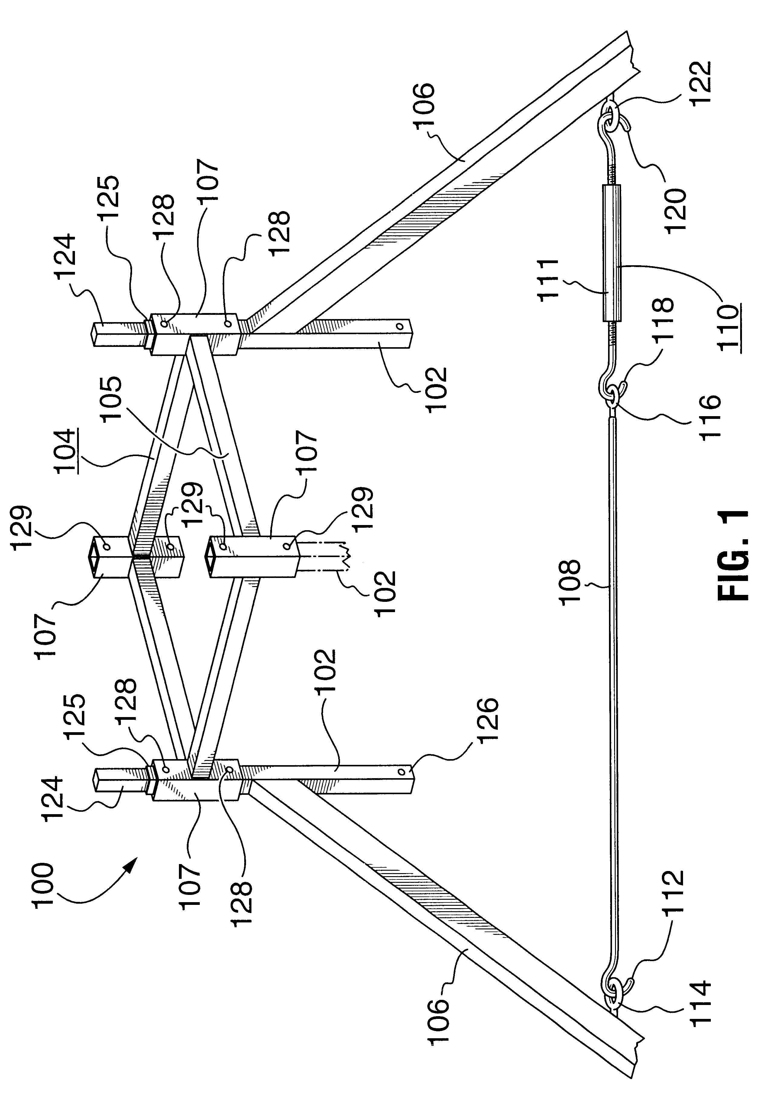
(a) Description of FIG. 1
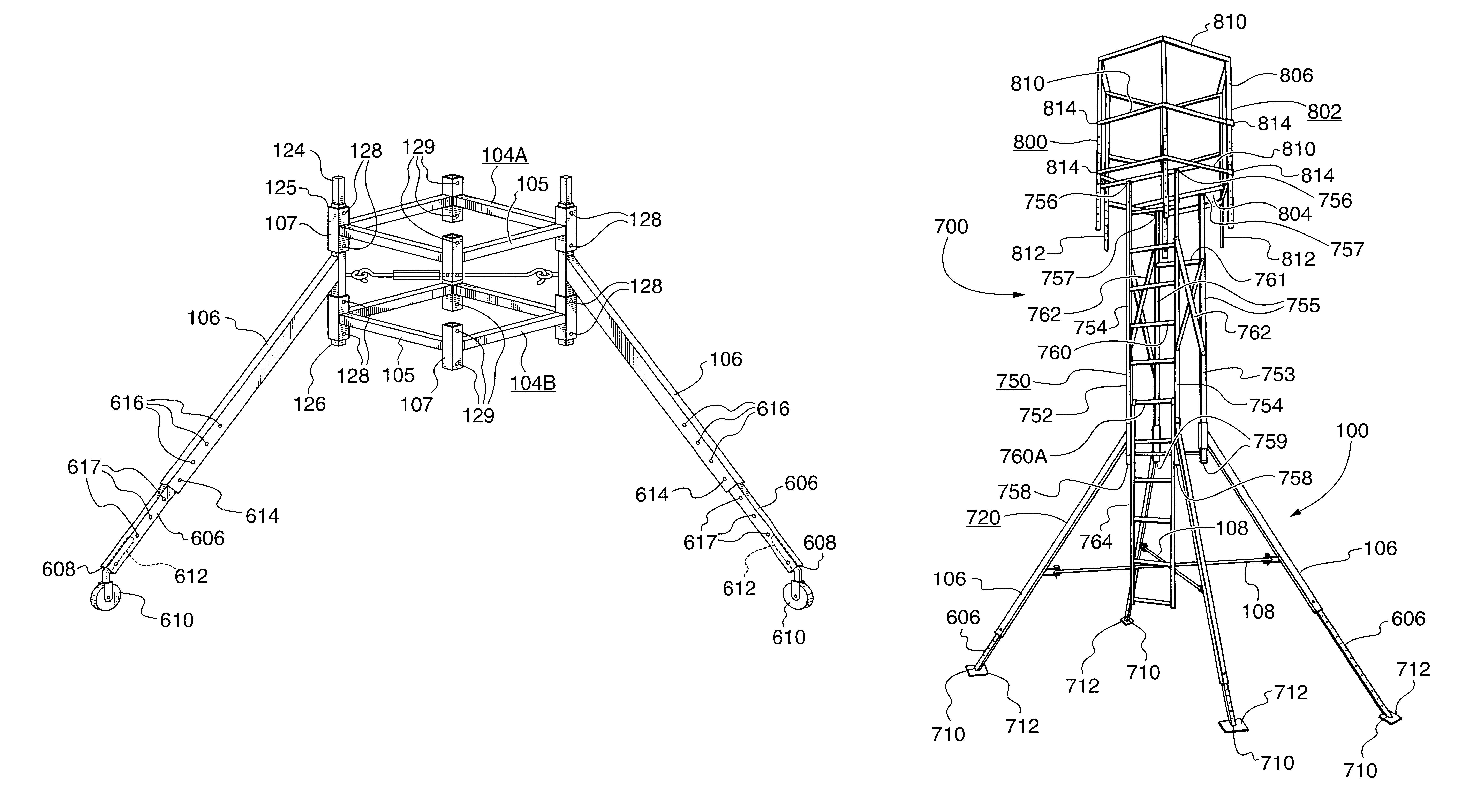
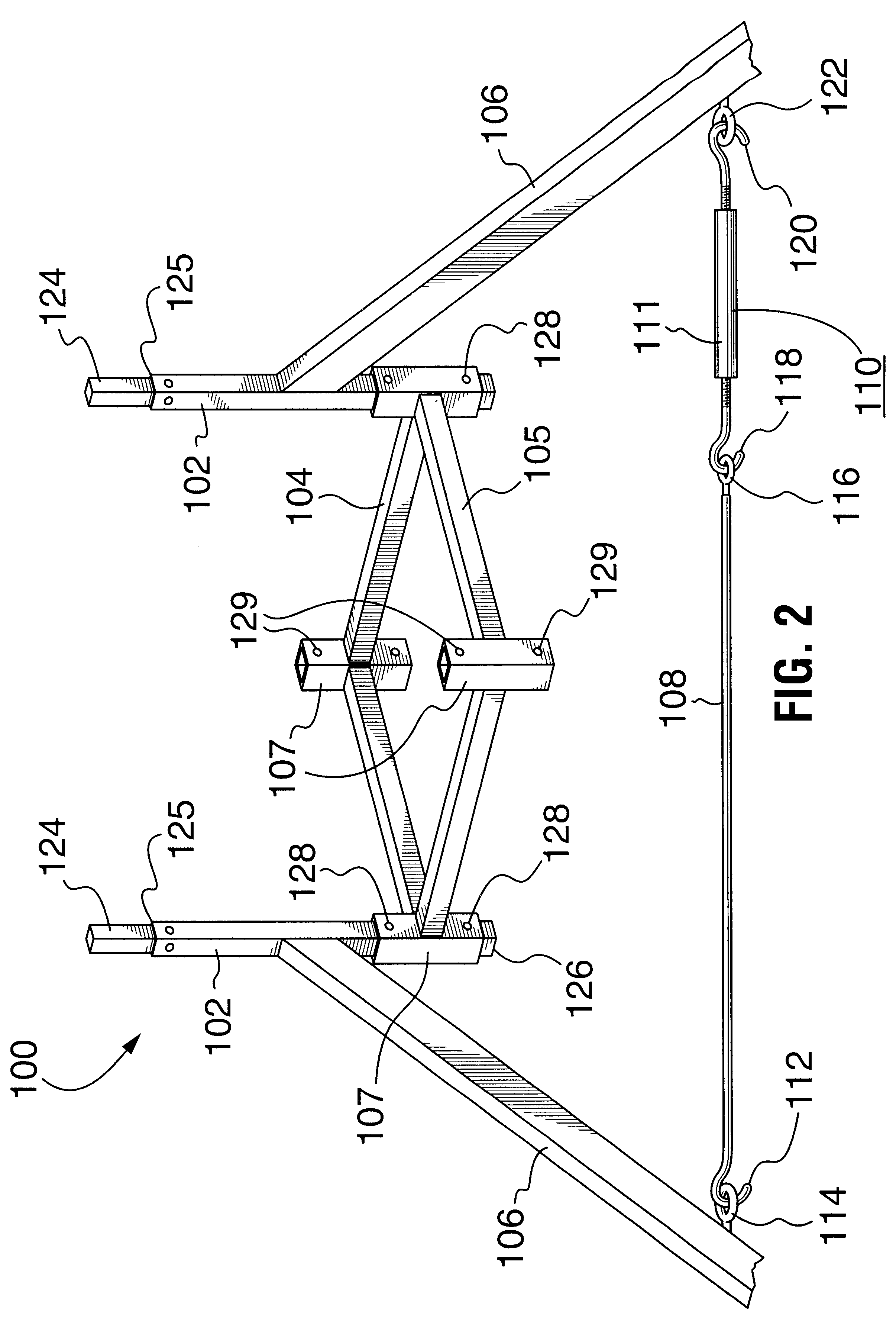
FIGS. 1 to 5 show several embodiments of the STAF according to an embodiment of an aspect of the present invention. The STAF 100 comprises four vertical posts 102 and a horizontal rectangular framework 104. This framework 104 includes four horizontal members 105 and four hollow vertical members 107. The interconnections to provide framework 104 are as follows:
The horizontal members 105 each connect to adjacent vertical members 107. Legs 106 are secured to associated vertical posts 102. Each leg 106 extends downwardly and outwardly. A first of two first stabilizing members 108 interconnects one set of nonadjacent, opposed legs, thereby providing a pair of interconnected legs. A second stabilizing member (not seen) interconnects the other non-adjacent legs 106. A first means 110 for applying a compressive force or extensive force to the interconnected non-adjacent legs 106 is configured to change the spacing (i.e., the footprint) between the pair of nonadjacen...
PUM
Abstract
A stability alignment frame useful for the erection of a observation or hunting stand includes a plurality of vertical posts. A horizontal framework interconnects adjacent posts and a leg is secured to an associated vertical post. Each leg extends downwardly and outwardly. A first stabilizing member interconnects non-adjacent, opposed legs, thereby providing a plurality of interconnected legs. Structure is provided for applying a force to the interconnected legs to change the spacing between the bases of a pair of the interconnected legs, thereby providing a wedging action between the stability alignment frame and an elevated vantage point. This provides a stable base for supporting the elevated vantage point.
Description
(1) BACKGROUND OF THE INVENTION(a) Aims of the InventionThe present invention relates generally to a support base frame, denoted herein as a "Stability Alignment Frame" or "STAF". This STAF can be used, for example, as the stable base for the erection of an observation and hunting stand, which is configured for ease of portability and disassembly.(b) Description of the Prior ArtHunters, nature watchers, or guards usually require an elevated means to obtain a higher vantage point for observing games, animals, birds or people. Many such means have been described in the prior art, but these seem to have one or other drawbacks.U.S. Pat. No. 3,967,694 (Woolfolk Sr., 1976), U.S. Pat. No. 5,327,993 (Stark, Sr., 1994), and U.S. Pat. No. 6,035,968 (Morales, 2000) each disclose platforms for fishing, hunting or the like that are collapsible and portable.U.S. Pat. No. 4,086,980 (Shortes et al., 1978), U.S. Pat. No. 4,274,508 (Hughes et al., 1981), and U.S. Pat. No. 5,791,436 (Talley, Sr., 1998...
Claims
Application Information
Patent Timeline
Application Date:The date an application was filed.
Publication Date:The date a patent or application was officially published.
First Publication Date:The earliest publication date of a patent with the same application number.
Issue Date:Publication date of the patent grant document.
PCT Entry Date:The Entry date of PCT National Phase.
Estimated Expiry Date:The statutory expiry date of a patent right according to the Patent Law, and it is the longest term of protection that the patent right can achieve without the termination of the patent right due to other reasons(Term extension factor has been taken into account ).
Invalid Date:Actual expiry date is based on effective date or publication date of legal transaction data of invalid patent.