System and method for a dryer rough-in box with contoured vent receptacle and formed grommet

a dryer and rough-in box technology, applied in the field of system and method of dryer rough-in box, can solve the problems of reducing the efficiency of the dryer, kinking, and unsuitability, and achieve the effect of reducing kinking

Inactive Publication Date: 2004-05-04
JACK ARGUIJO JOINT VENTURE
View PDF8 Cites 13 Cited by
  • Summary
  • Abstract
  • Description
  • Claims
  • Application Information

AI Technical Summary

Benefits of technology

A primary object and feature of the present invention is to provide a holding system that stores at least a portion of the flexible exhaust hose from a dryer within a wall. It is a further object and feature of the present invention to provide such a system that guides the flexible exhaust hose from a dryer to the duct connection, when the dryer is placed in close proximity to the wall, thereby reducing kinking.
It is a further object and feature of the present invention to provide an exhaust duct-extension, which allows the system to be installed more conveniently than the prior art.
It is a further object and feature of the present invention to provide a grommet specifically designed to snugly fit a gas conduit, which allows the system to be installed more conveniently than the prior art.
It is a further object and feature of the present invention to provide an exhaust duct-extension, which allows convenient to installation through an exterior wall

Problems solved by technology

Since the duct inlet commonly protrudes several inches from the wall, the dryer is limited in how close it can be set against the wall by the space required for the flexible exhaust hose and duct inlet.
Moving the clothes dryer in a close proximity to the wall may result in kinking and / or crushing the flexible hose, reducing the efficacy of the exhaust vent, thereby diminishing the efficiency of the clothes dryer.
Although solutions to this problem have been sought, they are unsuitable and far from optimal.
As such, the bottom corners of the box presents spaces wherein the dryer hose may be trapped, and therefore kinked.
The Harpenau rough-in box, as those like it, is deficient in that installing a recessed receptacle with a planar bottom surface can result in kinking of the flexible exhaust hose when the hose gets pushed back into the receptacle.
This, in turn, has deleterious effects, as mentioned above.
As such, although the In-O-Vate dryer rough-in box provides a slanted surface for guiding the compression of a retracting flexible dryer hose, the box is still deficient in that the dryer hose may still get trapped in the vertex / corner, thereby reducing the free flow of the dryer exhaust.
Installing a system that requires adapting an existing duct through an opening in a receptacle is problematic.
It can be more difficult and less aesthetically pleasing than making a connection that is hidden within the wall.
Also, the junction between the receptacle and the duct may not conveniently achieve a tight seal, which is desirable for insulation, pest control and aesthetic reasons, etc.
Additionally, there may not be enough existing duct within the wall to install the receptacle at the desired height, requiring installation of a separate piece of duct--an additional step that adds inconvenience.

Method used


Image

  • System and method for a dryer rough-in box with contoured vent receptacle and formed grommet
  • System and method for a dryer rough-in box with contoured vent receptacle and formed grommet
  • System and method for a dryer rough-in box with contoured vent receptacle and formed grommet

Examples


Embodiment Construction

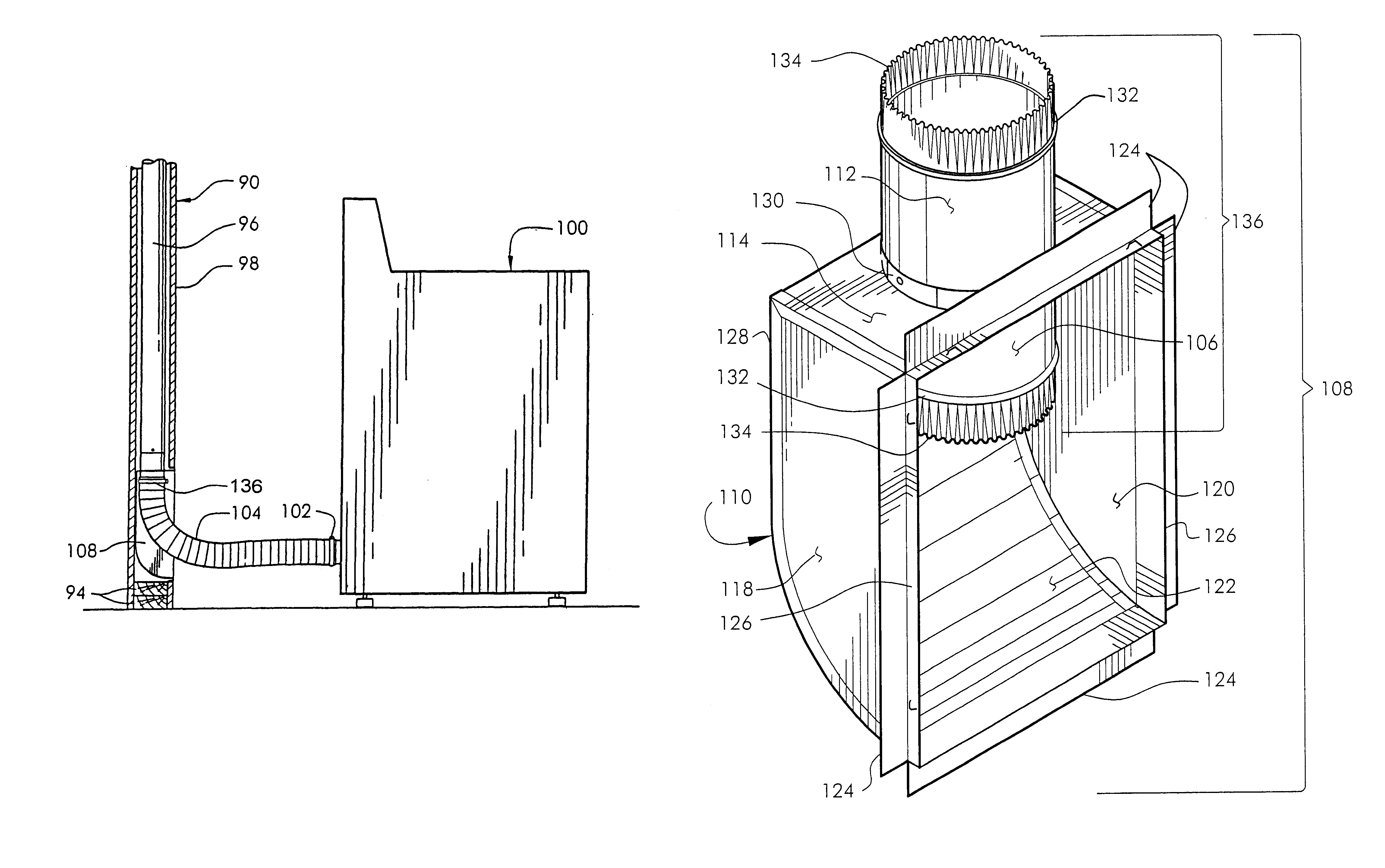
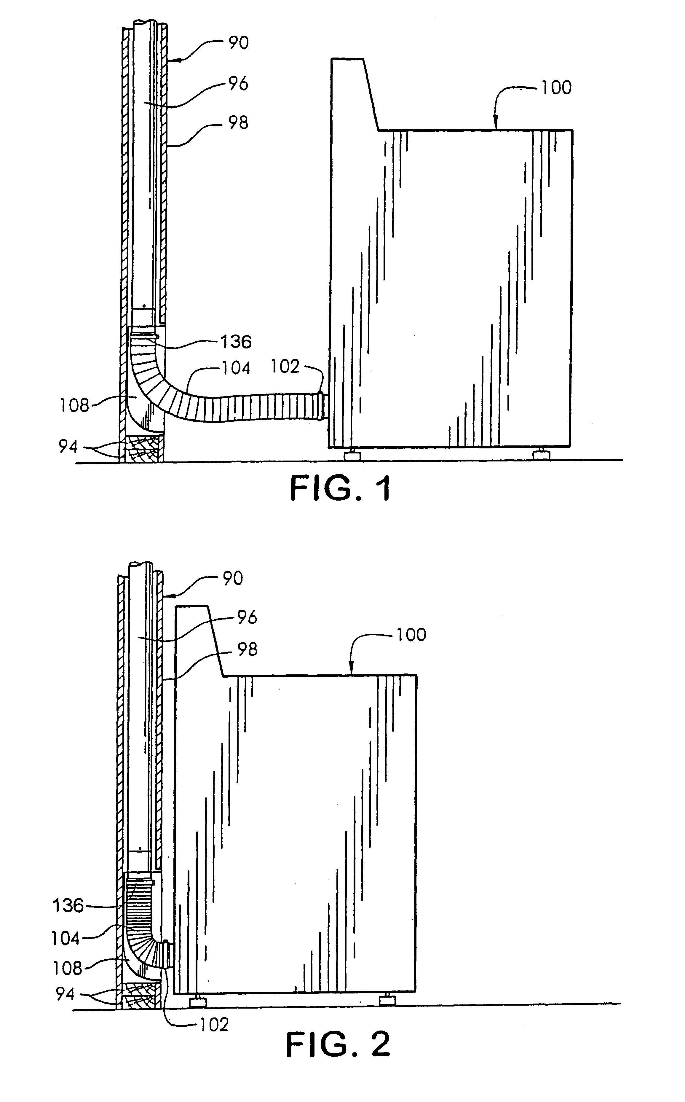
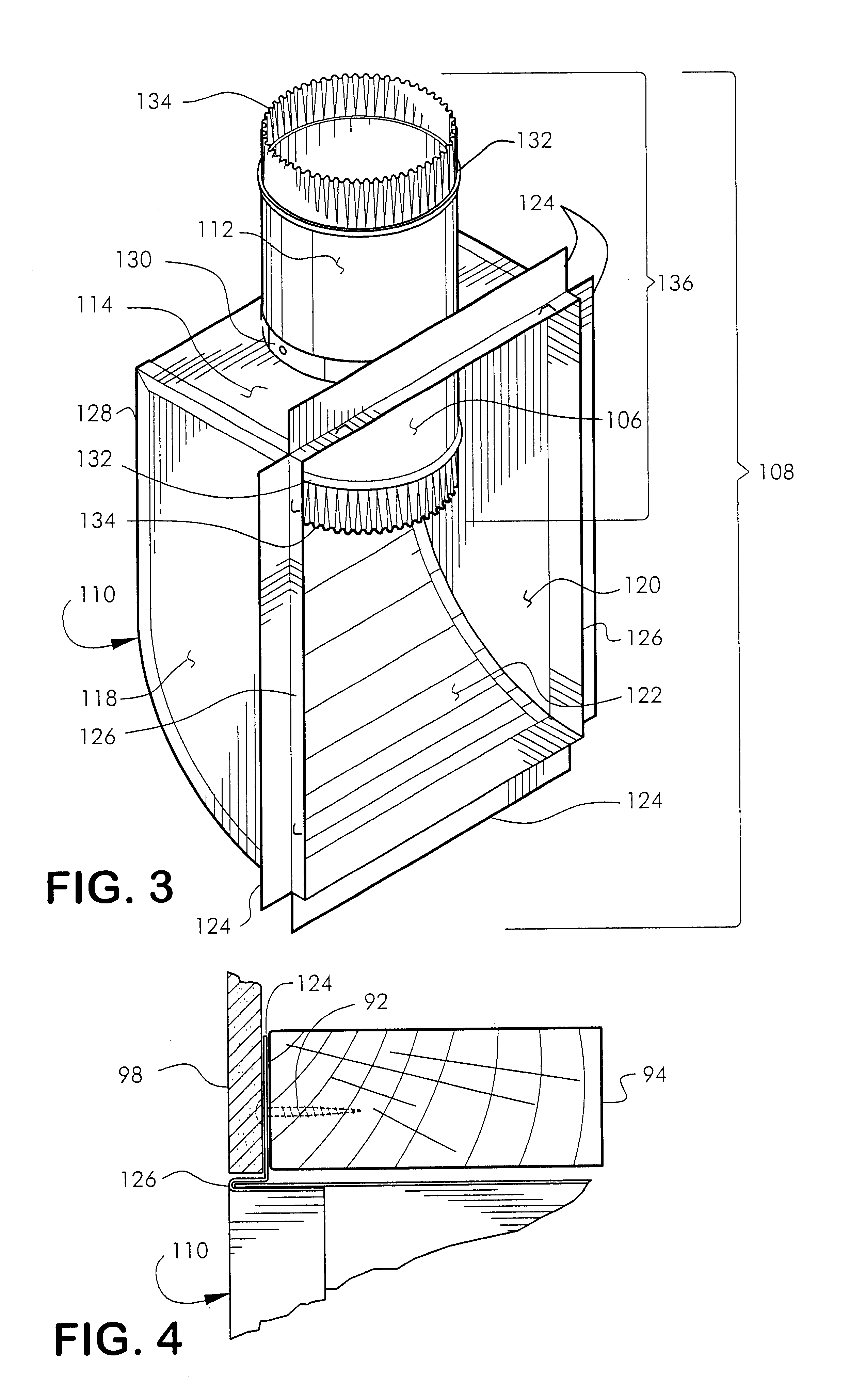
Reference is now made to the drawings. FIG. 1 is a side view of a dryer 100 located at a distance from a wall 90 (shown in cross-section). Dryer exhaust vent 102 is connected to one end of flexible exhaust hose 104, as shown. Other end of flexible exhaust hose 104 is connected to lower duct-extension 106 of the holding system 108 installed within the wall 90, as shown. Upper duct-extension 112 is connected to exhaust duct 96 within wall 90, as shown. Preferably, duct-extension 136 comprises lower duct-extension 106 and upper duct-extension 112, as shown. Preferably, exhaust from the dryer travels first through flexible exhaust hose 104, then through duct-extension 136, and finally into exhaust duct 96, which is preferably vented to the outside.

FIG. 2 is a side view of the dryer 100 in close proximity to the typical wall 90 (shown in cross-section). Flexible exhaust hose 104 fits within space in wall provided by holding system 108, allowing dryer 100 to be placed close to wall 90 wit...


PUM


Abstract

A system for holding a portion of the flexible exhaust hose from a dryer within a wall, thereby allowing the dryer to be placed in close proximity to the wall is provided. The system provides a dryer rough-in box including a contoured surface for smoothly guiding the flexible exhaust hose to minimize bending and kinking. An integral segment of duct is provided to allow for convenient and aesthetic installation, where the connection of the system to the duct in the was is hidden within the wall. Additionally, the rough-in box includes an opening structured and arranged to snugly fit a gas line is provided, thereby aiding in.

Description

This invention relates to providing a system and method for recessed dryer rough-in box with contoured vent receptacle and grommet that allows installation of a clothes dyer in a closer proximity to a wall.Typically, a connection is made from the dryer to a flexible exhaust hose. The other end of the flexible exhaust hose is then connected to a duct inlet protruding from a wall adjacent the dryer. It is often desirable to place the clothes dryer as close to the wall as possible in order to save space, prevent materials from falling behind the clothes dryer, and for aesthetics, etc. The flexible exhaust hose allows movement of the dryer as for cleaning, repair, etc., without the inconvenience of disconnecting it from the exhaust duct. Since the duct inlet commonly protrudes several inches from the wall, the dryer is limited in how close it can be set against the wall by the space required for the flexible exhaust hose and duct inlet. Moving the clothes dryer in a close proximity to t...

Claims


Application Information

Patent Timeline
Patent Type & Authority Patents(United States)
IPC IPC(8): D06F58/20
CPCD06F58/20
Inventor ARGUIJO, RALPH L.JACK, IVAN H.
Owner JACK ARGUIJO JOINT VENTURE
Why Eureka
Try Eureka