Touch switch layout and method for the control of a touch switch
- Summary
- Abstract
- Description
- Claims
- Application Information
AI Technical Summary
Benefits of technology
Problems solved by technology
Method used
Image
Examples
Embodiment Construction
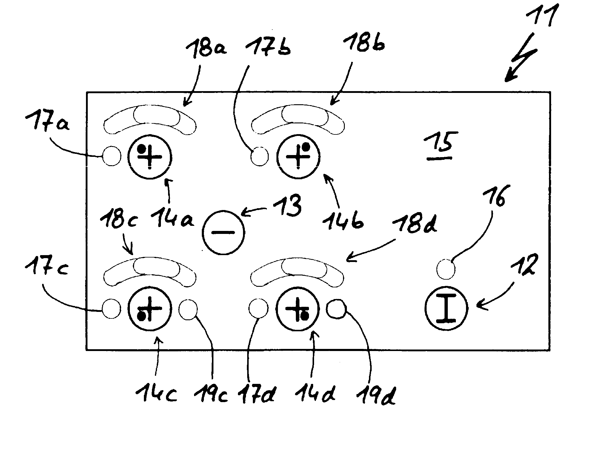
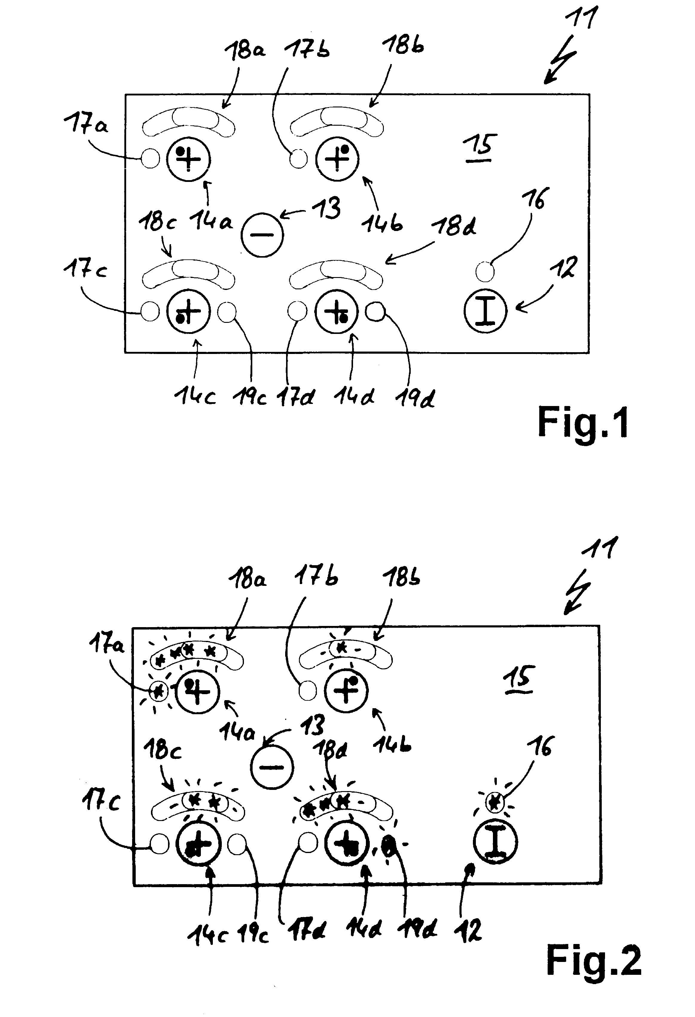
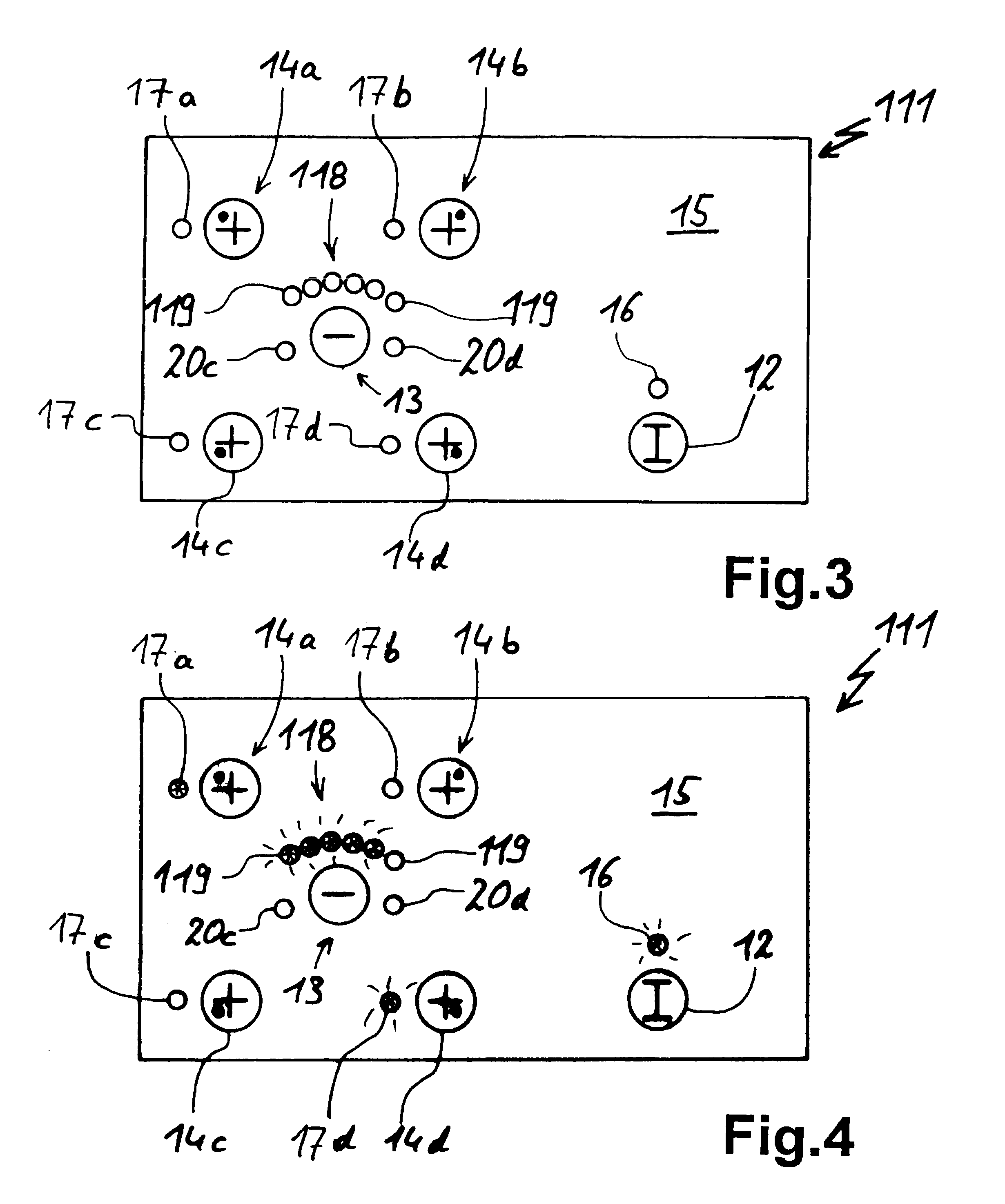
FIG. 1 shows a touch switch layout 11, which is shown in the operated state in FIG. 2. It has several touch switches, namely an on-off switch 12, a central minus or negative switch 13 and four selection / plus or positive switches 14a-d grouped around the negative switch 13. The individual touch switches 12 to 14a-d are represented by corresponding, imprinted decoration on the top of a contact or touch surface 15. In exemplified manner this is provided in an area of the glass ceramic hob, which is provided with imprints. These selection and positive switches 14a-d represent the four hot points of the hob, which is shown by the dot relative to the cross or plus sign.
An on-off switch 12 has an activatable LED 16, which lights up when the hob is switched on. No display is associated with the central negative switch 13. Display means in the form of a selection LED 17a-d and bar LED displays 18a-d arranged in circular arc form are associated with the individual selection switches. As is in...
PUM
 Abstract
Description
Claims
Application Information
 - R&D
- Intellectual Property
- Life Sciences
- Materials
- Tech Scout
- Unparalleled Data Quality
- Higher Quality Content
- 60% Fewer Hallucinations
Browse by: Latest US Patents, China's latest patents, Technical Efficacy Thesaurus, Application Domain, Technology Topic, Popular Technical Reports.
© 2025 PatSnap. All rights reserved.Legal|Privacy policy|Modern Slavery Act Transparency Statement|Sitemap|About US| Contact US: help@patsnap.com


