Pulley driving system

a technology of driving system and pulley, which is applied in the direction of dynamo-electric converter control, multiple dynamo-motor starters, magnetic circuit shape/form/construction, etc., can solve the problems of increasing the amount of torque and difficulty in satisfying the amount of torque, so as to prevent the effect of reducing the amount of torque rippl

Inactive Publication Date: 2004-05-18
MITSUBISHI ELECTRIC CORP
View PDF19 Cites 44 Cited by
  • Summary
  • Abstract
  • Description
  • Claims
  • Application Information

AI Technical Summary

Benefits of technology

to provide a rotary electromechanical device which can prevent a reduction in the amount of torque and reduce torque ripples as well as a pulley driving system employing such a rotary electromechanical device.
In still another form of the invention, the multiple motor sections are provided on both sides of the pulley section in the axial direction of the rotary shaft. This arrangement makes it possible to balance forces exerted on the pulley section and distribute forces exerted on the pulley section and the motor sections and, therefore, there is no need to unnecessarily increase the mechanical strength of connecting parts between the pulley section and the motor sections and the physical size of the system can be reduced.

Problems solved by technology

The rotary electromechanical device employing the aforementioned skewed slots and the rotary electromechanical device disclosed in Japanese Laid-open Utility Model Publication No. 4-97459, however, has a problem that it is difficult to obtain the amount of torque satisfying the aforementioned requirements due to a reduction in facing surface areas of magnetic poles of the rotors and magnetic poles of the stators.
In particular, a so-called magnetic pole concentrated winding type rotary electromechanical device, in which coils are wound closely around teeth formed on a core of a stator, has a problem that a reduction in the amount of torque increases if a conventional torque ripple reduction method as stated above is used.

Method used


Image

  • Pulley driving system
  • Pulley driving system
  • Pulley driving system

Examples


first embodiment

Now, embodiments of the invention are described with reference to the accompanying drawings.

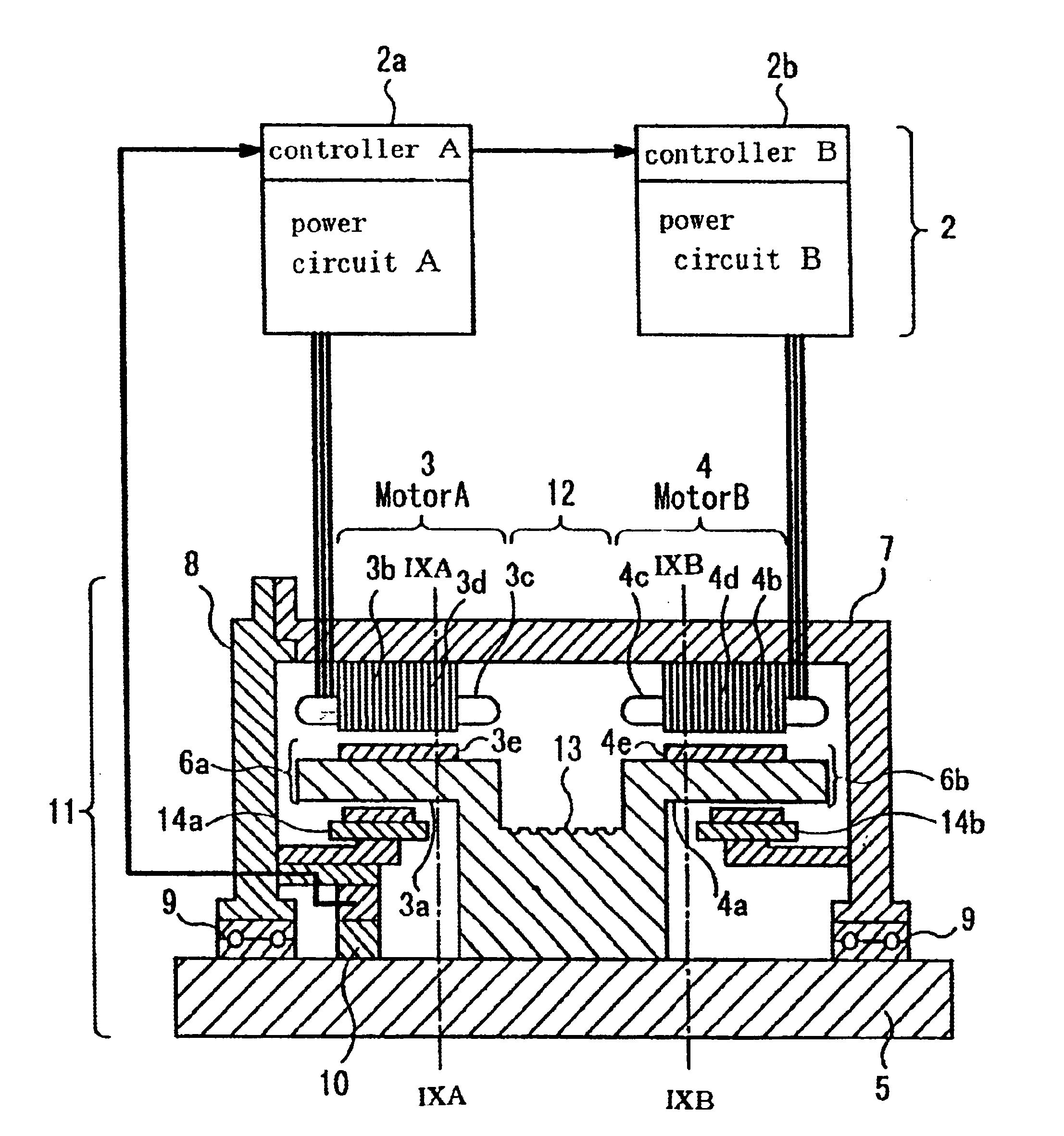
FIG. 1 is a partially sectional diagram showing the construction of a rotary electromechanical device according to a first embodiment of the invention, in which designated by the numeral 1 is a rotary machine section, and designated by the numeral 2 is a driver section for driving the rotary machine section 1. Since the rotary machine section 1 is generally axially symmetric, only one side of a rotary shaft 5 is shown in FIG. 1.

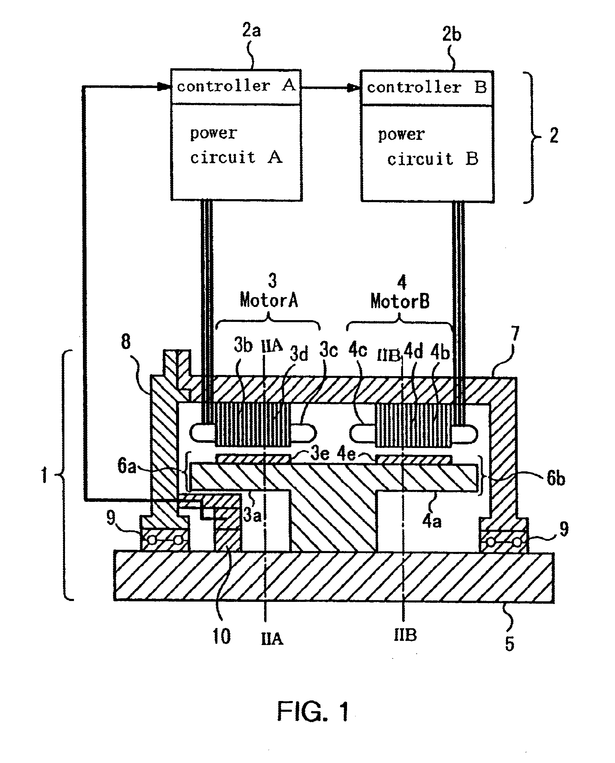
The rotary machine section 1 incorporates a motor A3 and a motor B4. Rotors 6a, 6b integrally formed with yokes (iron cores) 3a, 4a are fixedly mounted on the rotary shaft 5. Permanent magnets 3e are fixed to the yoke 3a and permanent magnets 4e are fixed to the yoke 4a. A stator 3b fixed to a frame 7 and the rotor 6a together constitute the motor A3 while a stator 4b fixed to the frame 7 and the rotor 6b together constitute the motor B4. The motor A3 and the motor B4 ...

second embodiment

FIG. 8 is a partially sectional diagram showing the construction of a built-in motor type pulley driving system according to a second embodiment of the invention employing the rotary electromechanical device of the above-described first embodiment. In FIG. 8, the same reference numerals as used in the first embodiment indicate elements identical or equivalent to those of the first embodiment, and a detailed description of such elements is omitted.

As illustrated in FIG. 8, a hoisting machine 11 includes a pulley section 12 provided at the center, a motor A3 and a motor B4 provided respectively on the left and right of the pulley section 12, wherein yokes (iron cores) 3a, 4a of rotors 6a, 6b of the motor A3 and the motor B4 and a pulley 13 of the pulley section 12 form a single structure which is fixedly mounted on a rotary shaft 5. This means that the motor A3 and the motor B4 are integrally mounted on a common axis on the rotary shaft 5 with the pulley 13 disposed in between.

Brakes ...

third embodiment

FIG. 10 is a sectional diagram showing a construction according to a third embodiment of the invention, in which the same reference numerals as used in FIG. 8 indicate elements identical or equivalent to those shown in the foregoing discussion.

In this embodiment, a frame is divided at its center into two parts, a first frame section 7a and a second frame section 7b. This construction makes it possible to configure stators 3b, 4b of motors A3 and B4 by shrink-fitting the first frame section 7a on the stator 3b and the second frame section 7b on the stator 4b and, then, assembling the first and second frame sections 7a, 7b. Since the stators 3b and 4b can be assembled independently of each other by shrink fit process which requires considrably high positioning accuracy during manufacture, this embodiment helps improve productivity.

As an alternative, the frame may be divided into four discrete parts, that is, first and second frame sections 7a, 7b and brackets 8a, 8b as shown in FIG. 1...


PUM


Abstract

A rotary electromechanical device includes a first motor including a first stator and a first rotor, a second motor including a second stator and a second rotor, and variable power supplies for driving the respective motors independently of each other, The motors are arranged in series along the axial direction of a rotary shaft. Magnetic poles of the same polarity of the rotors are located at uniform angular positions around the rotary shaft while magnetic poles of the stator of the motor and magnetic poles of the stator of the second motor are displaced from each other in the circumferential direction of the rotary shaft.

Description

BACKGROUND OF THE INVENTION AND RELATED ART STATEMENTThe present invention relates to a rotary electromechanical device used in a field in which stringent requirements are imposed with respect to torque characteristics and for small torque ripples, as well as to a pulley driving system using the rotary electromechanical device.In a rotary electromechanical device like an induction motor, for example, grooves, or so-called slots, for accommodating coils are formed in the proximity of an air gap by punching an iron core in a stator or a rotor, and there occur areas of high and low magnetic flux densities in a magnetic field formed in the air gap due to a difference in reluctance between the slots and the iron core. For this reason, magnetic fluxes formed in the air gap contain a lot of harmonic components and, therefore, there occur torque variations in the induction motor. The torque variations occurring in the induction motor are referred to as torque ripples, and it is necessary to...

Claims


Application Information

Patent Timeline
Patent Type & Authority Patents(United States)
IPC IPC(8): H02K7/10H02K16/00H02K29/06H02K29/03H02K3/28H02K1/18H02K21/14H02K21/24H02K37/00
CPCH02K7/1008H02K16/00H02K29/03H02K29/06H02K37/00
Inventor DAIKOKU, AKIHIROHASHIGUCHI, NAOKI
Owner MITSUBISHI ELECTRIC CORP
Why Eureka
Try Eureka