High security manhole insert cover
a manhole insert and high-security technology, applied in the field of manhole insert covers, can solve problems such as the potential for security breaches in areas
- Summary
- Abstract
- Description
- Claims
- Application Information
AI Technical Summary
Benefits of technology
Problems solved by technology
Method used
Image
Examples
first embodiment
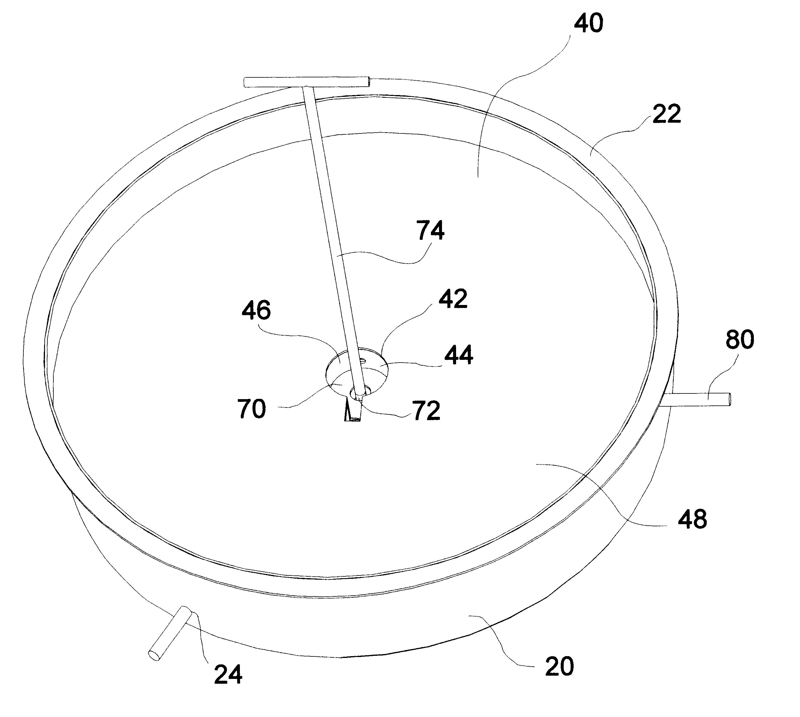
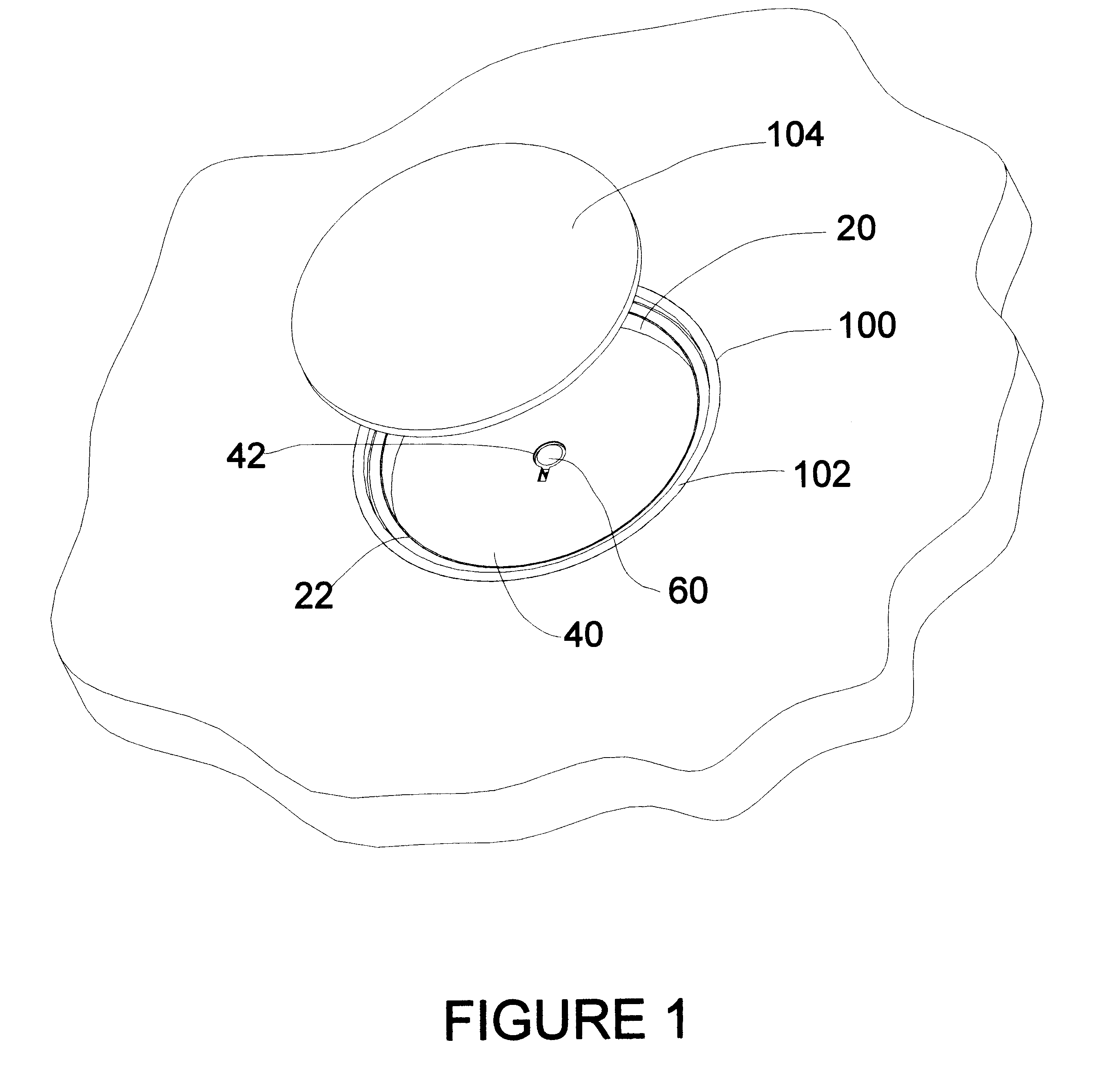
The rotatable locking means 70 is shown as two embodiments in the drawings. In the first embodiment, shown in FIGS. 4, 5, 7 and 8, the rotatable locking means 70 is a spiral cam 90a having a plurality of spiral slots 92 machined in the spiral cam 90a with a central hole 94a. This spiral cam 90a is attached to the lower plate 30 by a cam support pedestal 76, FIG. 5, having a central shaft 78 extending upward from the lower plate 30 engaging the central hole 94a. Attached above the central hole 94a, further attached to the spiral cam 90a is the central slot 72, also FIG. 5. The spiral cam 90a is thus rotated by turning the inserted slot key 74, FIG. 12 within the central slot 72 rotating the spiral cam 90a clockwise and counter clockwise. A plurality of extendable first locking arms 80a connect within the spiral slots 92 by cam bearings 84a positioned on a first end 82a of the first locking arms 80a, FIG. 8, which allow the first end 82a of the first locking arms 80a to move freely wi...
second embodiment
In the manhole insert, shown in FIGS. 9-13, the rotatable locking means 70 is provided by a flanged cam 90b, FIG. 9, having a plurality of extending flanges 91 incorporated into an outer perimeter 93 of the flanged cam 90b, said flanged cam 90b having a central hole 94b. This flanged cam 90b is also attached to the lower plate 30 by a cam support pedestal 76 having a central shaft 78 extending upward from the lower plate 30 engaging the central hole 94b, FIG. 11. Attached above the central hole 94b, further attached to the flanged cam 90b is the central slot 72. The flanged cam 90b is thus rotated by turning the inserted slot key 74 within the central slot 72 rotating the flanged cam 90b clockwise and counter clockwise, FIG. 12.
In this second embodiment, a plurality of second locking arms 80b are not directly connected to the flanged cam 90b, but each second locking arm 80b slideably engages a support bracket 81 attached to the perimeter rim 20, aligned with the locking arm holes 24...
PUM
 Abstract
Description
Claims
Application Information
 - R&D
- Intellectual Property
- Life Sciences
- Materials
- Tech Scout
- Unparalleled Data Quality
- Higher Quality Content
- 60% Fewer Hallucinations
Browse by: Latest US Patents, China's latest patents, Technical Efficacy Thesaurus, Application Domain, Technology Topic, Popular Technical Reports.
© 2025 PatSnap. All rights reserved.Legal|Privacy policy|Modern Slavery Act Transparency Statement|Sitemap|About US| Contact US: help@patsnap.com


