Display device

a display device and display technology, applied in the field of display devices, can solve the problems of inability to recognize one pixel as white, inability to display graininess more clearly, and easy to occur color split (or color separation) and other problems, to achieve the effect of less graininess in images

Inactive Publication Date: 2004-05-25
MITSUBISHI ELECTRIC CORP
View PDF6 Cites 25 Cited by
  • Summary
  • Abstract
  • Description
  • Claims
  • Application Information

AI Technical Summary

Benefits of technology

An object of the present invention is to provide a display device in which co

Problems solved by technology

However, conventional delta-arrangement pixels PD have a problem of visibility in that "color split (or color separation)" easily occurs as compared to conventional trio-arrangement pixels PT.
However, when a visual angle between subpixels exceeds one minute angle, an observer s

Method used


Image

  • Display device
  • Display device
  • Display device

Examples


Embodiment Construction

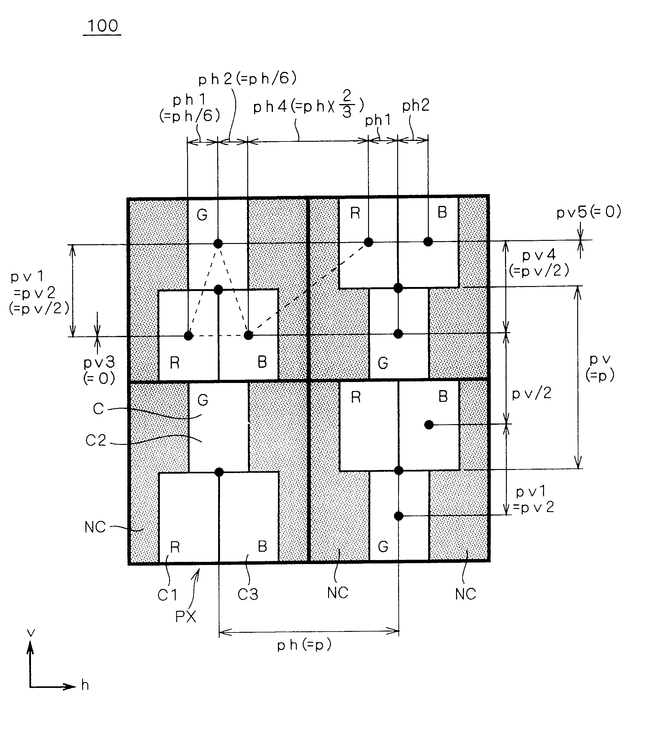
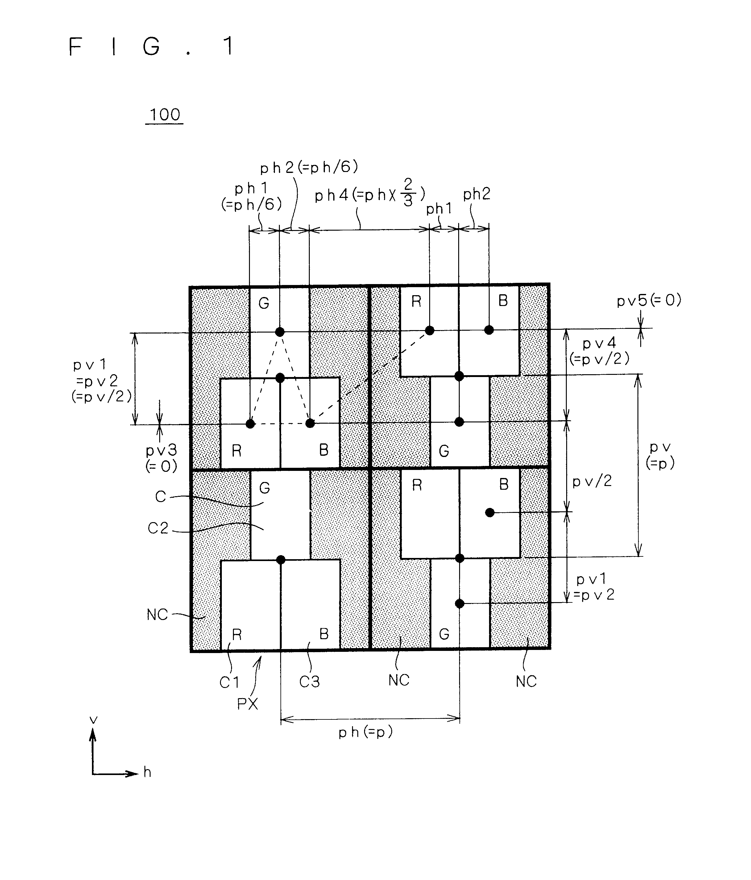
FIG. 1 is a schematic plan view showing a display device 100 according to a first preferred embodiment. A display of the display device 100 includes a plurality of pixels PX aligned in a first (here, vertical) direction v and a second (here, horizontal) direction h perpendicular to the first direction v and arranged as a whole in a matrix form in the plan view of the display. FIG. 1 shows four pixels PX arranged in a matrix of 2.times.2 as an example. An arrangement interval (hereinafter also briefly referred to as "interval") between adjacent pixels PX in the first direction v is set in pv, and an interval between adjacent pixels PX in the second direction h is set in ph.

The arrangement interval between adjacent pixels PX is given as an interval (distance) between pixel centers of the adjacent pixels PX. The center of a pixel PX is given as an intersection of lines passing through midpoints of respective dimensions in the first and second directions v and h. Conversely, the center ...


PUM


Abstract

Components of an arrangement interval in first and second directions (v, h) between first to third subpixels (C1, C2, C3) in a pixel (PX) satisfy the following expressions: pv1=pv2=pv/2; pv3=0; and ph1=ph2<ph/3. Components of the arrangement interval in the first and second directions (v, h) between two pixels (PX) adjacent to each other in the second direction (h) satisfy the following expressions: pv4=pv/2 (=p/2); pv5=0; and ph4>ph/3. Pixels (PX) adjacent to each other in the first direction (v) have the same arrangement of the first to third subpixels (C1, C2, C3).

Description

BACKGROUND OF THE INVENTION1. Field of the InventionThe present invention relates to a display device such as a plasma display panel (hereinafter also referred to as PDP), and more particularly to a display device in which color split (or color separation) is difficult to occur and which presents less graininess in images.2. Description of the Background ArtTrio- (or stripe-) arrangement pixels and delta-arrangement pixels exemplify matrix type displays having pixels arranged in a matrix form. FIGS. 19 and 20 are schematic plan views showing a conventional trio-arrangement pixel PT and a conventional delta-arrangement pixel PD, respectively. Although each including three subpixels (or cells) C for emitting the three primary colors of light, red (R), green (G) and blue (B), respectively, these pixels differ from each other in arrangement of the subpixels C. A subpixel for emitting red, for example, is hereinafter also referred to as "red subpixel".For ease of comparison, both of the ...

Claims


Application Information

Patent Timeline
IPC IPC(8): H01J17/49H01J11/12H01J11/14H01J11/22H01J11/24H01J11/26H01J11/32H01J11/34H01J11/36H01J11/42H01J11/44
CPCH01J11/12H01J11/34G09G3/291
Inventor HARADA, SHIGEKINAGAI, TAKAYOSHISANO, KOUYURA, SHINSUKE
Owner MITSUBISHI ELECTRIC CORP
Why Eureka
Try Eureka