Method of constructing a rail track on a track-receiving concrete slab

a concrete slab and rail track technology, applied in the direction of temporary pavings, rail fasteners, ways, etc., can solve the problems of slow laying and chocking of rails

Inactive Publication Date: 2004-06-22
ALSTOM TRANSPORT TECH SAS
View PDF7 Cites 12 Cited by
  • Summary
  • Abstract
  • Description
  • Claims
  • Application Information

AI Technical Summary

Benefits of technology

An object of the present invention is to remedy that drawback by proposing a method of constructing a rail track on a concrete slab in which the rails can be put in place in the channels much faster.

Problems solved by technology

That technique is fast for laying the concrete, but it suffers from the drawback of being slow for laying and chocking the rails.

Method used


Image

  • Method of constructing a rail track on a track-receiving concrete slab
  • Method of constructing a rail track on a track-receiving concrete slab

Examples


Embodiment Construction

To make the drawing clearer, only those elements necessary to understanding the invention are shown.

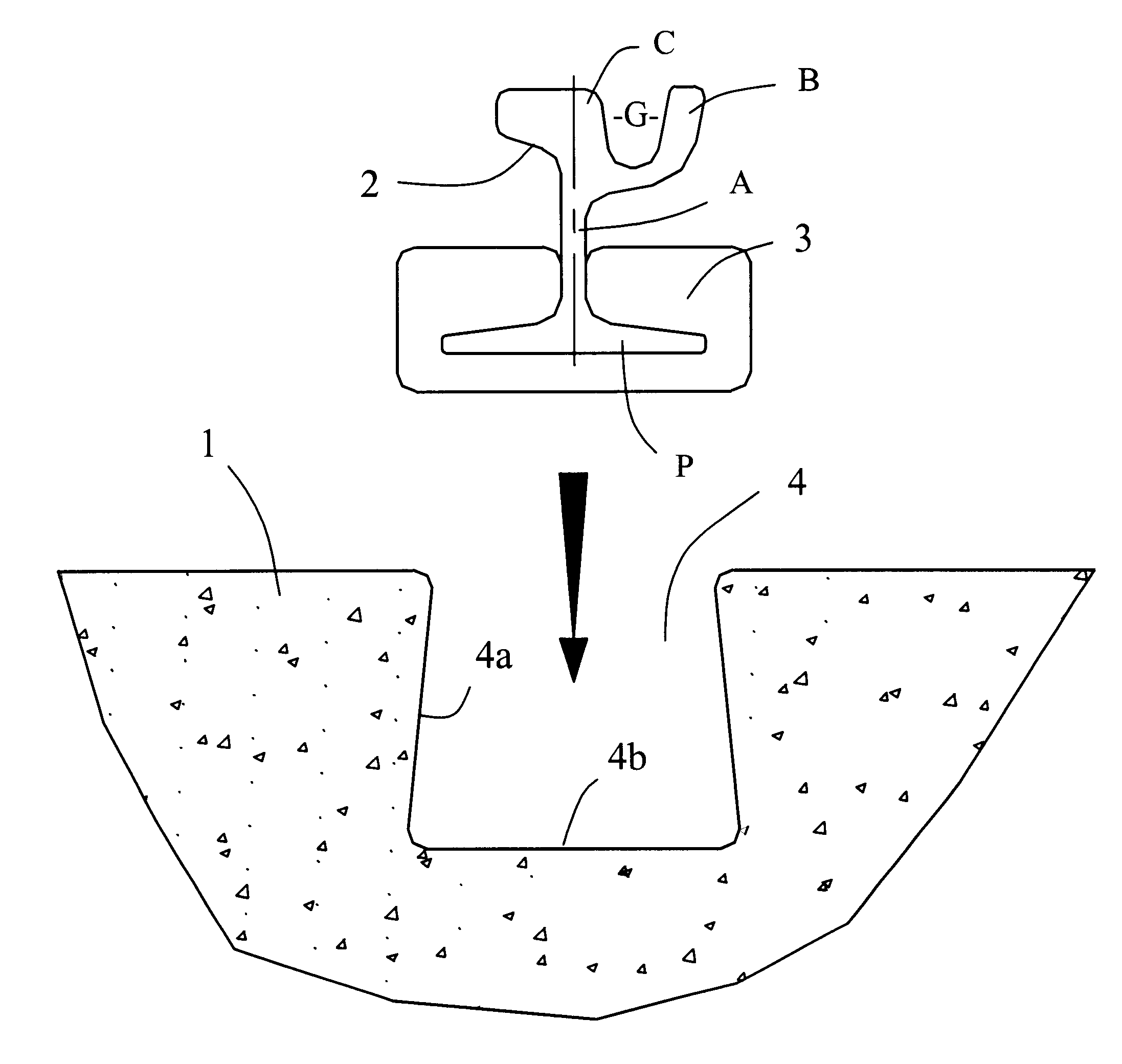
FIG. 1 is a detail view of a track-receiving concrete slab 1 serving to receive one or more stretches of grooved rail 2. For each stretch of rail 2, the slab 1 is provided with a channel 4 delimited by side edges 4a and by a bottom 4b.

For example, the track-receiving slab 1 may be made by a construction method known to the person skilled in the art as the "slip-form" method, and it is advantageously cast on a clean subgrade (not shown in the figure). In such a method, the slab 1 is built continuously by means of a machine carrying a form and moving along the path of the rail track, wet concrete being pumped or deposited in front of the machine, the form imparting a predetermined shape to it as the machine advances. The overall shape of the concrete slab 1 is substantially rectangular, the channels 4 serving to receive the stretches of rails 2 being formed by corresponding grooves in t...


PUM


Abstract

A method of constructing a rail track on a track-receiving concrete slab provided with channels serving to receive the rails of the rail track, wherein, after the concrete forming the track-receiving slab has set, it comprises at least the following steps:a) the stretches of rail are put in place above the channels in the track-receiving slab, each rail having a foot coated with a casing of resilient material; andb) the foot as coated with its casing is inserted into the channel by force.

Description

The invention relates to a method of constructing a rail track on a track-receiving concrete slab provided with channels serving to receive the rails of the rail track. The invention is particularly applicable to constructing rail tracks for a subway or a tramway.Methods of constructing rail tracks are known that use a track-receiving concrete slab, such methods being increasingly frequently used because they make it possible for the rate of construction of the track-receiving slab to be very fast. In such methods, wet concrete is generally continuously cast by an automatic machine that follows the path of the track to be built, the machine having a sliding mold or "slip form" provided with two grooves for forming the channels in the slab of concrete. After the concrete has set, the rails are laid in segments in the channels, they are welded end-to-end, and they are then chocked manually to the desired height, and spaced apart to the desired gauge, with clearance being left relative...

Claims


Application Information

Patent Timeline
Patent Type & Authority Patents(United States)
IPC IPC(8): E01B9/62E01B21/04E01B21/00E01B9/00E01B1/00E01B21/02E01B37/00
CPCE01B9/62E01B21/04E01B2201/10E01B2204/01E01B2204/09
Inventor EHRSAM, JEANSKIFIC, YVAN
Owner ALSTOM TRANSPORT TECH SAS
Why Eureka
Try Eureka