Tape transport servo system and method for a computer tape drive

Inactive Publication Date: 2004-06-22
IBM CORP
View PDF24 Cites 96 Cited by
  • Summary
  • Abstract
  • Description
  • Claims
  • Application Information

AI Technical Summary

Problems solved by technology

However, since the tape drive is a 5.25" form fact

Method used


Image

  • Tape transport servo system and method for a computer tape drive
  • Tape transport servo system and method for a computer tape drive
  • Tape transport servo system and method for a computer tape drive

Examples


Embodiment Construction

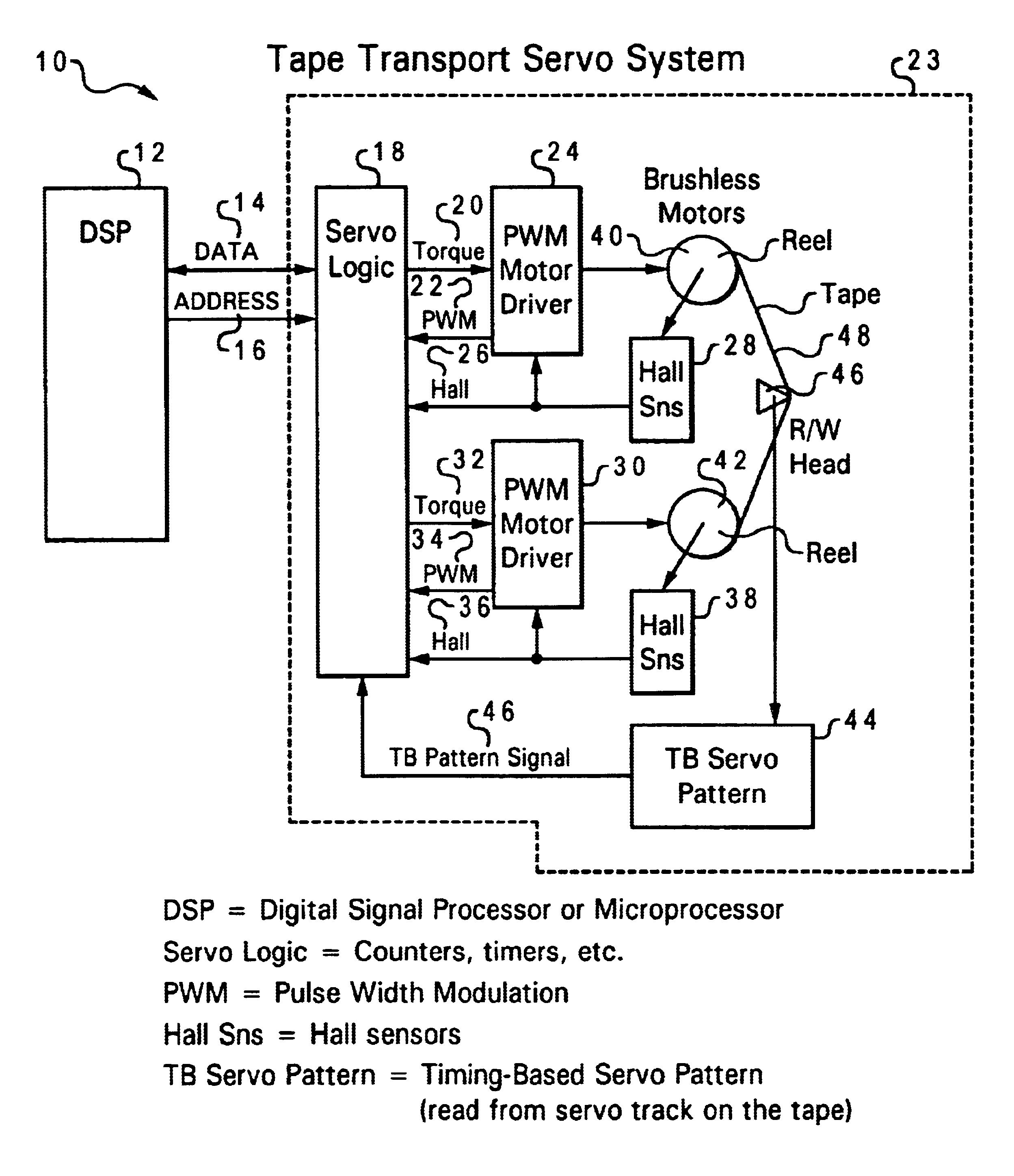
The present invention provides a tape transport servo system 10 and method that do not make use of tachometers and / or encoders to derive tape velocity and position. The present invention tape transport servo system 10 and method derive velocity and position of the tape 48 from a primary and direct manner and also a secondary or alternative manner, especially when transient conditions exist which prevent the primary or direct manner from being used. The present invention tape transport servo system 10 and method rely on deriving the velocity from both a primary velocity source and signal and a secondary velocity source and signal.

With reference now to the figures and in particular with reference to FIG. 3, the overall present invention tape transport system 10 is shown. The system 10 has a digital signal processor or microprocessor (DSP) 12. DSP communicates data 14 between and directs addresses 16 to a servo motor control system 23. The DSP 12 communicates directly with the servo lo...


PUM


Abstract

A tape transport servo system and method that do not make use of tachometers and/or encoders to derive tape velocity and position are provided. The tape transport servo system and method derive velocity and position of the tape from a primary and direct manner and also a secondary or alternative manner, especially when the primary or direct manner cannot be used. The tape transport servo system and method control a tape drive and moves a tape between one reel driven by one motor to another reel driven by another motor. The tape is read by a recording head composed of data readers, data writers and a dedicated set of servo read elements. A position and a velocity of the tape are determined from a primary velocity source when the tape is being read by the head. The position and the velocity of the tape are determined from a secondary velocity source when the tape is not being read by the head. The velocity of the tape is compared to a desired programmed reference velocity for the tape. The velocity of the tape is driven to the desired programmed reference velocity if the velocity is not equal to the desired velocity. The velocity of the tape is controlled by regulating the velocity and the driving currents of the motors. The tape transport servo system comprises a digital signal processor and a servo motor control system. The servo motor control system comprises a servo logic system, sensors, PWM motor drivers, power amplifiers, DACs, counters, computation systems, and a timing-based servo pattern monitoring system.

Description

1. Technical FieldThe present invention relates in general to a tape transport servo system and method for a computer drive and in particular to a tape transport servo system and method that eliminates the use of tape deck encoders and / or tape-path tachometers for controlling tape velocity and position. The present invention relates to a tape transport servo system and method that derives tape velocity from a primary velocity signal, such as from a servo track pre-recorded on the tape, and that also derives tape velocity from a secondary velocity signal, such as from pulse-width-modulation (PWM) signals driving two reel motors.2. Description of the Related ArtTape drives for computer systems have been in existence in the computer field. One type of tape drive, such as the Sapphire media tape drive, involves two reels of tape wherein one of the two reels is a supply reel and the other of the two reels is a take-up reel. The tape on the reels is typically a half inch (0.5") wide. The ...

Claims


Application Information

Patent Timeline
IPC IPC(8): G11B15/46G11B5/584
CPCG11B5/584G11B15/46
Inventor KOSKI, JOHN ALEXANDER
Owner IBM CORP
Why Eureka
Try Eureka