Shipping container for elongated articles

a technology for shipping containers and elongated objects, applied in the field of shipping containers, can solve the problems of increasing the material and labor costs of packing and shipping, the weight limit, and the use of relatively small containers

Inactive Publication Date: 2004-06-29
STABILUS
View PDF10 Cites 8 Cited by
  • Summary
  • Abstract
  • Description
  • Claims
  • Application Information

AI Technical Summary

Benefits of technology

In one embodiment of a shipping container constructed in accordance with the present invention, a protective member is interposed between the cushioning member and the lower ends of the receptacle members to prevent the elongated articles received within the receptacle members from penetrating the cushioning member. Preferably, the protective member includes a plastic sheet, where plastic is used to avoid rusting. The plastic sheet may include one or more drainage holes.
The shipping container, according to the invention, receives the elongated articles in vertical orientations with respect to the bottom of the container, which has the advantage of presenting all of the articles directly at the top. As mentioned above, past practice has involved packing the elongated articles on their sides, which presents only a row of side by side articles at any point of time in the process of unloading. Preferably, each article is received in an individual receptacle member, thus protecting each article from contact with any other article. In most cases, the articles need not be wrapped, inasmuch as the receptacle members provide sufficient protection against marring and damage of the articles by keeping them from contacting each other. The protruding upper parts of the elongated articles facilitate unloading the container by presenting a part of the article that can be grasped by hand or by a machine part.
In a preferred embodiment of the shipping container constructed in accordance with the present invention, the receptacle members are joined to each other, which provides additional stability to the receptacle member unit beyond that derived from having them in mutual contact and, in particular, facilitates unloading individual articles without risk of a loose receptacle member being withdrawn from the container with the elongated article.
In most cases, maximum density for shipping groups of containers dictates that the containers be rectangular in plan and side elevation. Round receptacle members are preferred over other shapes for strength. With rectangular containers and round receptacle members, maximum density of the receptacle members is attained by having them arranged in rows with the longitudinal axes of the receptacle members of each row lying in a plane and by staggering the receptacle members in a honeycomb fashion in which the receptacle members in adjacent rows are offset relative to each other in the direction of the planes of the rows by a distance equal to the outside radius of the receptacle members. The staggered rows, in addition to increasing the density, retain the possibility of easily loading the receptacle members row by row using automated loading equipment.
To minimize movements radially of the elongated articles having transverse external dimensions somewhat smaller than the corresponding inner dimensions of the receptacle members, an insert panel may be placed into the rigid container housing. The insert panel overlays the upper ends of the receptacle members and has a plurality of holes extending vertically therethrough. The holes are in vertical alignment with respective ones of the receptacle members such that the elongated articles inserted into the receptacle members extend vertically through the holes. The insert panel is stably supported laterally in the shipping container, preferably by shaping and sizing it so that at least portions of its perimeter engage the side wall(s) of the rigid container housing. The insert panel may rest on an upper end of the receptacle member unit. As previously indicated, the insert panel has holes in a pattern corresponding to the pattern of the receptacle members, centered with respect to the receptacle members, and of a size such as to accept, engage and stably support a portion of the article being shipped. The insert panel may be of a semi-rigid polymeric material, such as a blend of neoprene and nitrile rubber. Such a material provides a cushioning effect so that marring of the elongated articles is avoided.
In accordance with the present invention, the objects as described above have been met, and the need in the art for a shipping container for elongated articles that is economical to fabricate, easy to load and unload, provides excellent protection of the articles, is reusable, and allows the goods to be shipped without any disposable wrapping or packing materials, has been satisfied.

Problems solved by technology

Weight limits under worker safety standards have required the use of relatively small containers.
The need for foam or other protective material, which is conventionally disposed of, increases the material and labor costs of packing and shipping, generates environmental waste, and requires not only that personnel remove the gas springs but remove and dispose of the protective packing materials.

Method used


Image

  • Shipping container for elongated articles
  • Shipping container for elongated articles
  • Shipping container for elongated articles

Examples


Embodiment Construction

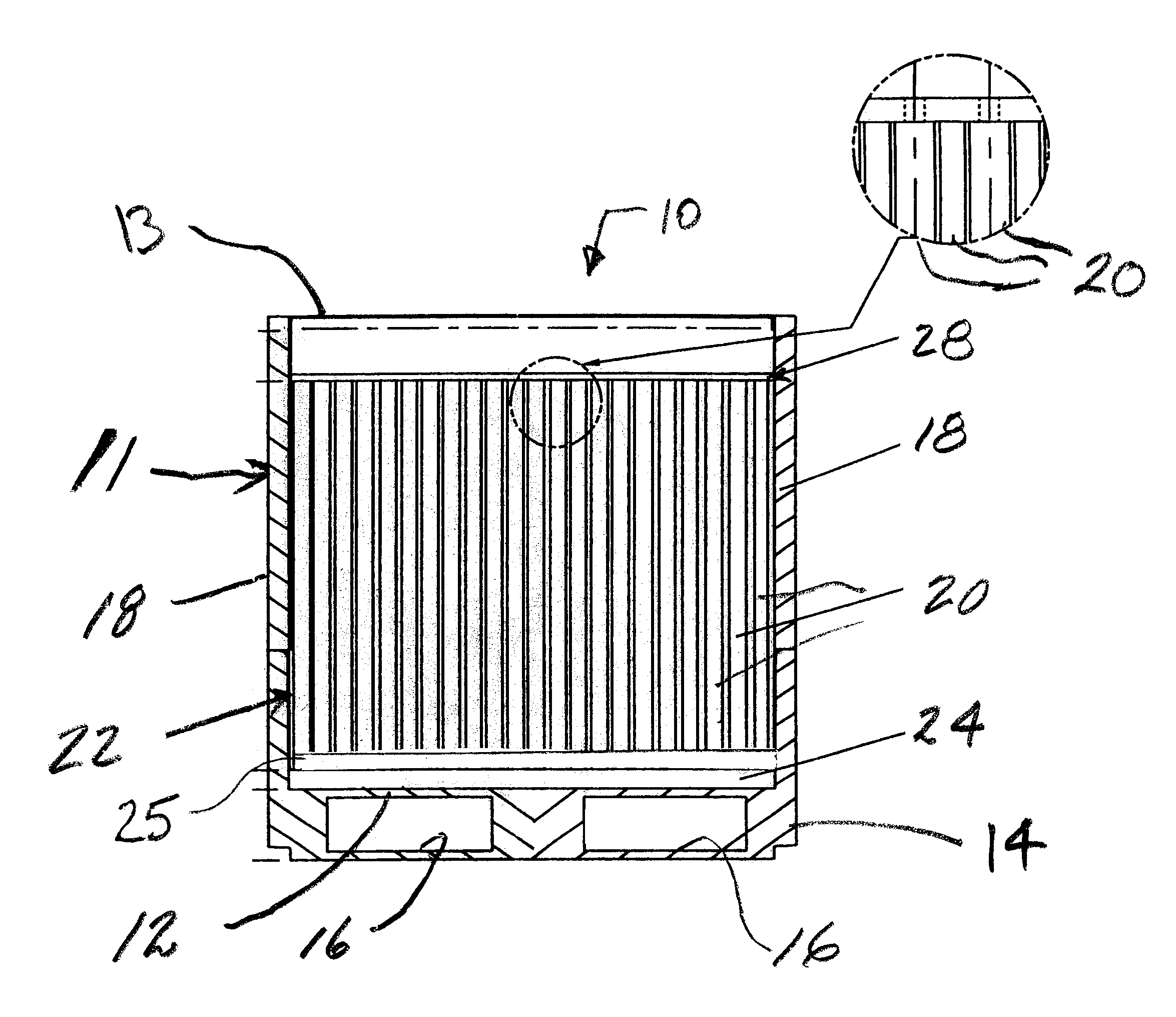
FIG. 1 is a side cross-sectional view of one embodiment of a shipping container 10 according to the present invention. The shipping container 10 includes a reusable rigid container housing 11 that is commercially available under the trademark "ROPAK" from Linpak Materials Handling of Georgetown, Ky. The rigid container housing 11 has a bottom wall 12 formed by the upper part of a pallet base 14, which includes two-way or four-way forklift guideways 16. As supplied, the ROPAK container housing 11 has collapsible side walls 18 forming an open upper end 13, preferably of rectangular shape in plan and all four side elevations--the collapsible feature is not used. The present invention may use any durable, reusable rigid container housing. Rectangular containers are, of course, preferred for maximum density when loaded in groups into a transport vehicle. The containers are stackable, and top covers (not shown) are available to close the topmost container of a stack.

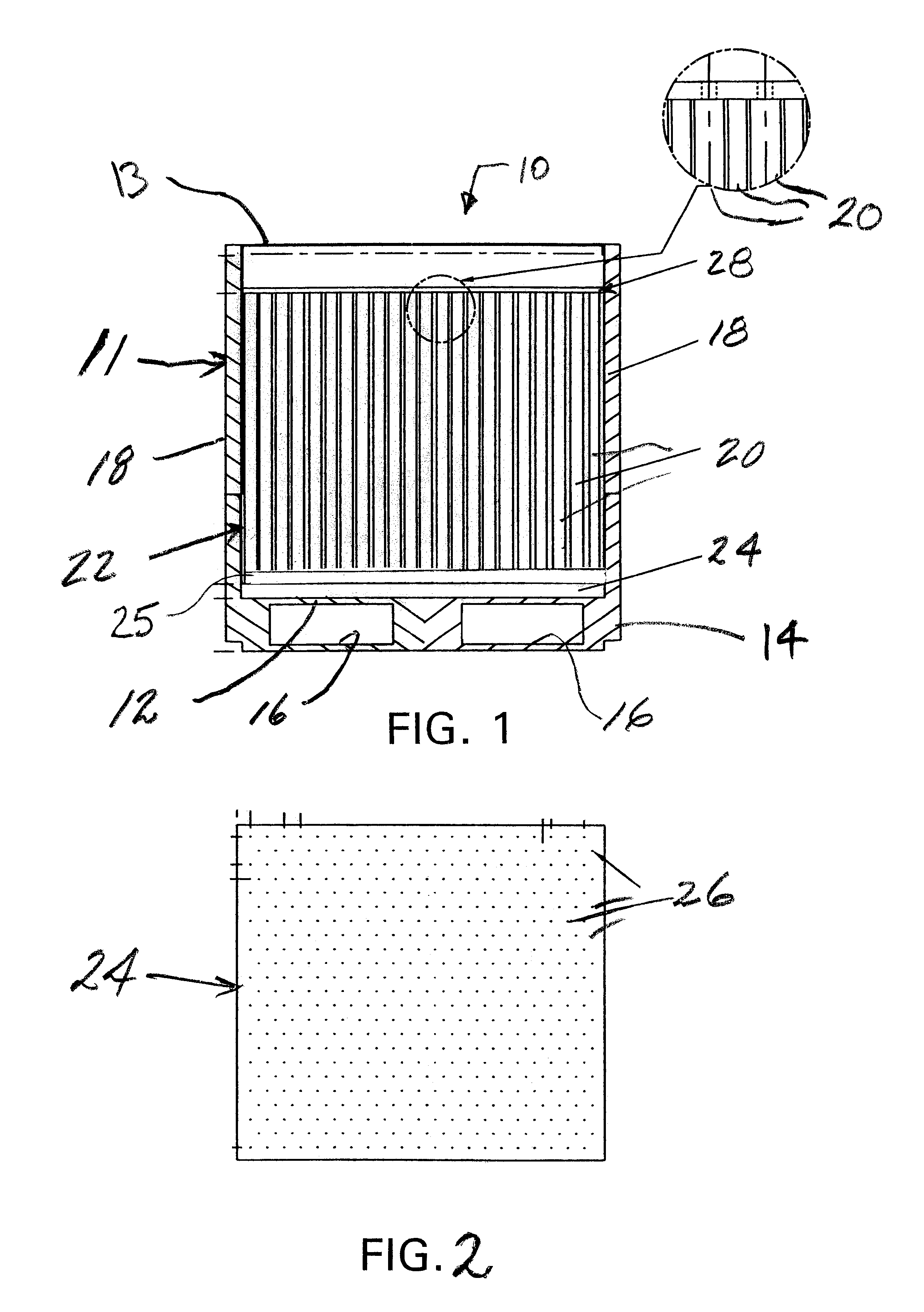
A cushioning member 24...


PUM


Abstract

A shipping container for elongated articles includes (a) a rigid container housing, including a bottom wall and at least one upright side wall enclosing the bottom wall, and having an open upper end for receiving a plurality of elongated articles, (b) a cushioning member supported by at least a portion of the bottom wall, and positioned between the bottom wall and the open upper end, and (c) a plurality of receptacle members, each defining a hollow channel having a lower end and an upper end and being adapted for holding one of the elongated articles, and being positioned with the lower end in proximity to the cushioning member and the upper end in proximity to the open upper end of the rigid container housing, the plurality of receptacle members being stably supported by each other and the at least one side wall of the rigid container housing.

Description

1. Field of the InventionThe present invention relates to shipping containers, and more particularly, to shipping containers for elongated articles.2. Description of the Related ArtAn important part of the business of a manufacturer is to provide ways of packing and shipping its goods to its customers in a manner that ensures that they are not damaged or marred and allows them to be unloaded easily and quickly. The manufacturer must also be attentive to keeping the costs of shipping materials and of preparing the goods for shipping low, making it as easy as possible to pack and load the goods into containers, and minimizing the use of disposable wrapping materials and containers for its goods.Gas springs are used for aiding the lifting of loads, such as the tailgates of automotive vehicles. In conventional shipping containers, gas springs have been packed for shipment to vehicle manufacturers (and other customers) horizontally in layers, with foam sheets separating the layers to pre...

Claims


Application Information

Patent Timeline
Patent Type & Authority Patents(United States)
IPC IPC(8): B65D81/107B65D85/20B65D19/02B65D6/18
CPCB65D19/02B65D81/107B65D85/20B65D2519/00034B65D2519/00208B65D2519/00288B65D2519/00815B65D2519/0086B65D2519/0096B65D2519/00975
Inventor RYALS, JEFFREY
Owner STABILUS
Why Eureka
Try Eureka