Locking and drive unit for a rotating body, in particular for motor vehicle wheels in a balancing machine

a technology of locking and driving unit and rotating body, which is applied in vehicle tyre testing, measurement devices, instruments, etc., can solve the problems of ring nuts, damage to machine parts, and sudden release of energy stored in elastic means, etc., and achieve the effect of operation effectiv

Inactive Publication Date: 2004-07-20
CORGHI
View PDF10 Cites 14 Cited by
  • Summary
  • Abstract
  • Description
  • Claims
  • Application Information

AI Technical Summary

Benefits of technology

An object of this invention is to obviate said drawback by a technical

Problems solved by technology

However this operation involves risks due to the fact that sometimes, during that stage in which the wheel is manually brought into contact with the contact surface and the pressing means are placed against the wheel, this latter can lock, due to friction, against any obstacle before adhering to the counteracting surface, for example against the cone or against the shaft, and hence not be perfectly in contact with the pressing means; in such cases, when the pneumatic cylinder-piston unit acting on the traction rod is discharged and the rod remains subjected only to the action

Method used


Image

  • Locking and drive unit for a rotating body, in particular for motor vehicle wheels in a balancing machine
  • Locking and drive unit for a rotating body, in particular for motor vehicle wheels in a balancing machine
  • Locking and drive unit for a rotating body, in particular for motor vehicle wheels in a balancing machine

Examples


Embodiment Construction

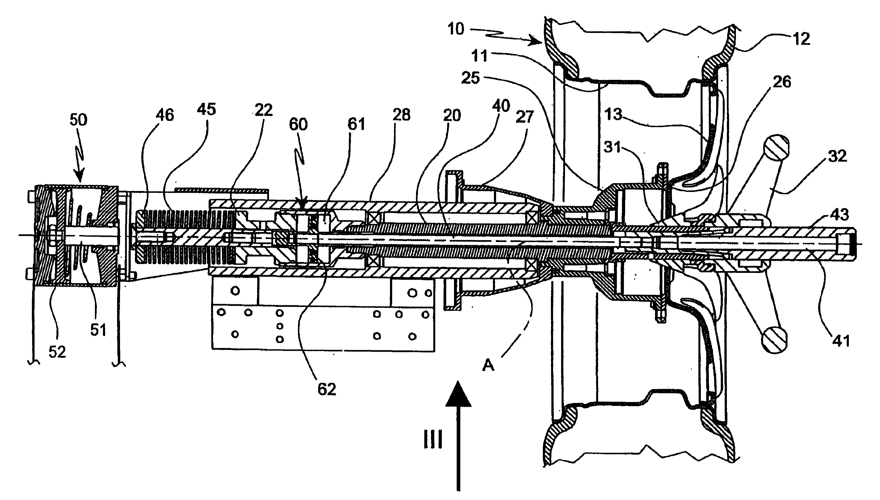
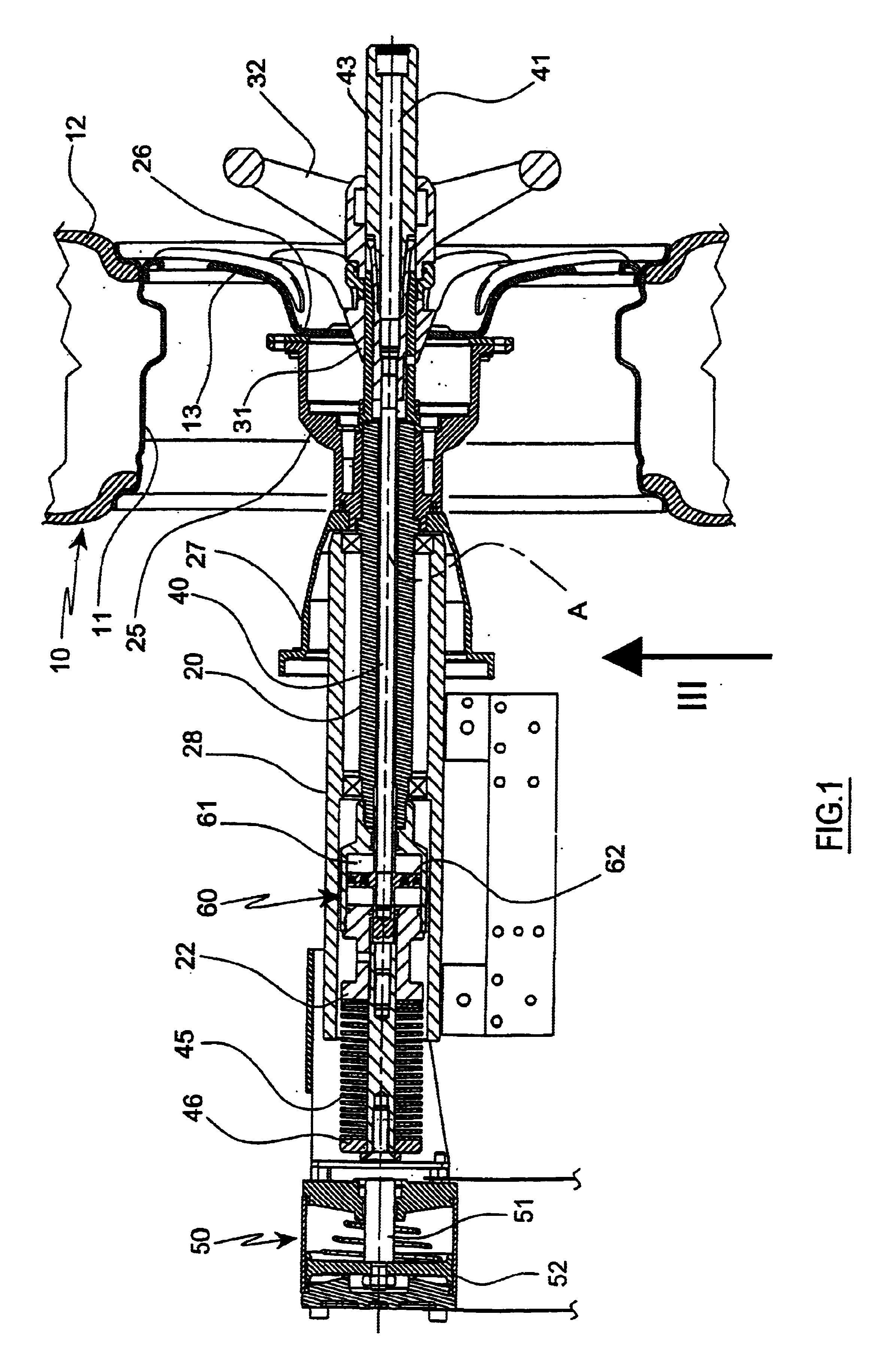
The unit shown in the figures is for a balancing machine for motor vehicle wheels 10, which usually comprise a wheel rim 11 having a transverse plate (web) 13 through the centre of which the axis of rotation of the wheel 10 passes, and a tire 12 applied to the outer surface of the wheel rim 11.

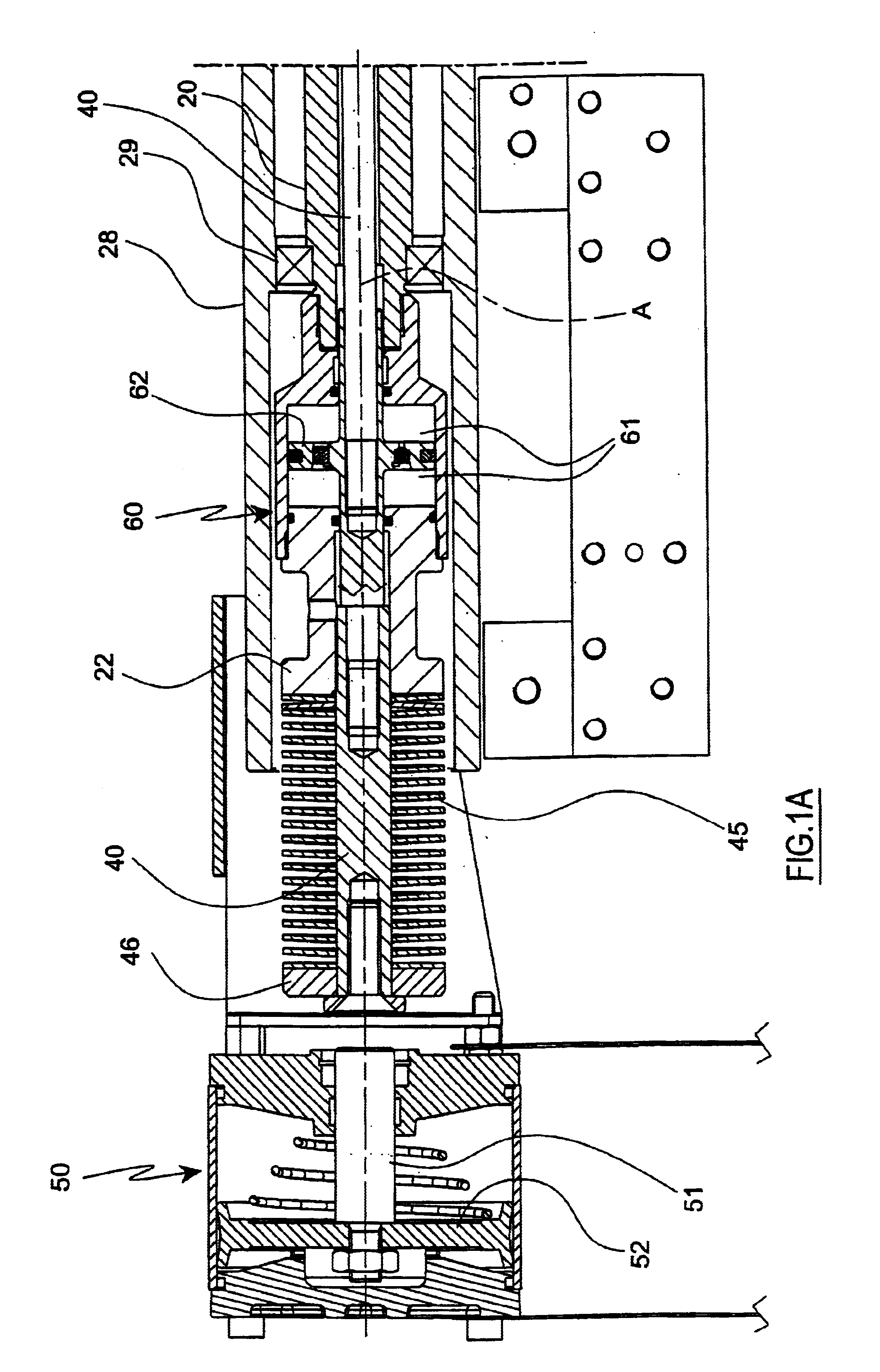
In accordance with to the known art, the unit of the invention comprises, for supporting the wheel (rotating body) 10 and rotating it about an axis A, a motorized main shaft 20 carrying flange means 25 which define a counteracting surface 26 for the wheel 10 perpendicular to the shaft axis A.

Specifically, the means 25 consist of a cap joined coaxially to the shaft 20 and traversed by the shaft, and having its concavity facing the front end thereof.

The front edge of the cap 25 defines a transverse plane which defines said counteracting surface 26.

To the rear of the cap 25 there is positioned a second cap 27, also coaxial to the shaft 20 and to which there are connected the transmission means (n...


PUM


Abstract

The locking and drive unit comprises, for supporting the rotating body (10) and rotating it about an axis A, a motorized main shaft (20) carrying flange means which define a counteracting surface (26) for the rotating body; and pressing means (31, 32) coaxial with the shaft (20) to axially press the rotating body (10) against said counteracting surface (26) and to lock it relative thereto; a traction rod (40) is associated with the main shaft (20), is movable axially relative thereto and is connected to the pressing means (31, 32) to pull them against the counteracting surface (26). Elastic thrust means (45) are connected to the traction rod (40) to axially pull, via this latter, the pressing means (31, 32) against the counteracting surface (26) to lock the rotating body relative thereto. The invention comprises an impact damping means (60) acting by mutual movement of two of its elements (61, 62) in the same direction as the axis of the main shaft (20) when the traction rod (40) is moved in the sense of pulling the pressing means (31, 32) towards the counteracting surface (26), one of said elements (61, 62) being rigid with the main shaft (20) and the other element being rigid with the traction rod (40).

Description

BACKGROUND OF THE INVENTIONThis invention relates to a locking and drive unit for a rotating body, in particular for motor vehicle wheels in a balancing machine.Typically the invention is provided for balancing motor vehicle wheels, however it can also be applied to other rotating bodies, such as flywheels.The unit to which the invention relates comprises: for supporting and driving the rotating body, a motorized main shaft carrying flange means which define a counteracting surface for the rotating body; pressing means coaxial with the shaft to axially press the rotating body against said counteracting surface and to lock it relative thereto; a traction rod associated with the main shaft and movable axially relative thereto, and connected to the pressing means to pull them against the counteracting surface; elastic thrust means (consisting for example of a robust precompressed spring) connected to the traction rod to axially pull, via this latter, the pressing means against the coun...

Claims


Application Information

Patent Timeline
IPC IPC(8): G01M1/00G01M1/04G01M1/16G01M17/02
CPCG01M1/045
Inventor CORGHI, REMO
Owner CORGHI
Why Eureka
Try Eureka