Wake control fin system and underwater exhaust system
- Summary
- Abstract
- Description
- Claims
- Application Information
AI Technical Summary
Benefits of technology
Problems solved by technology
Method used
Image
Examples
Embodiment Construction
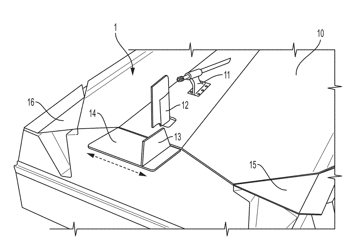
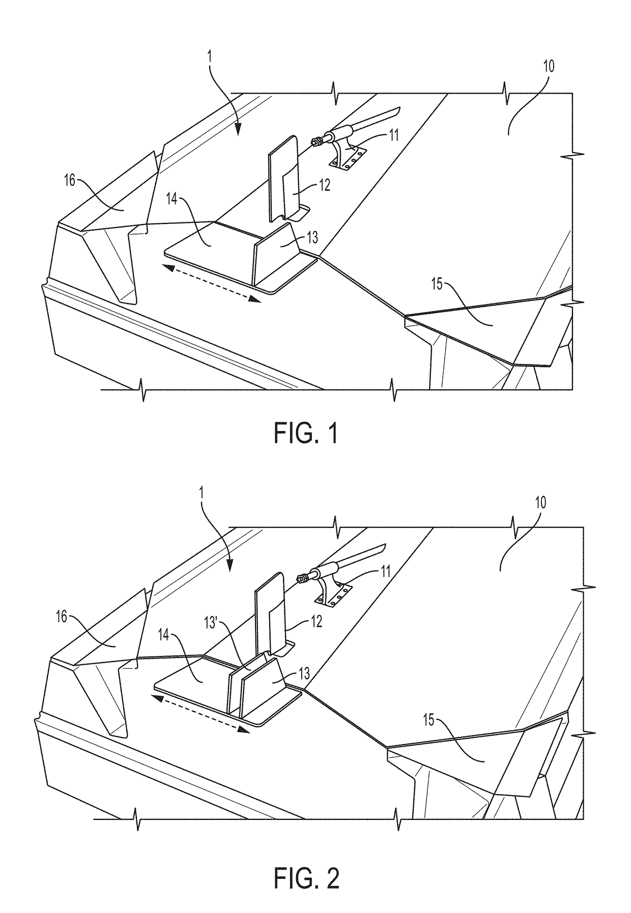
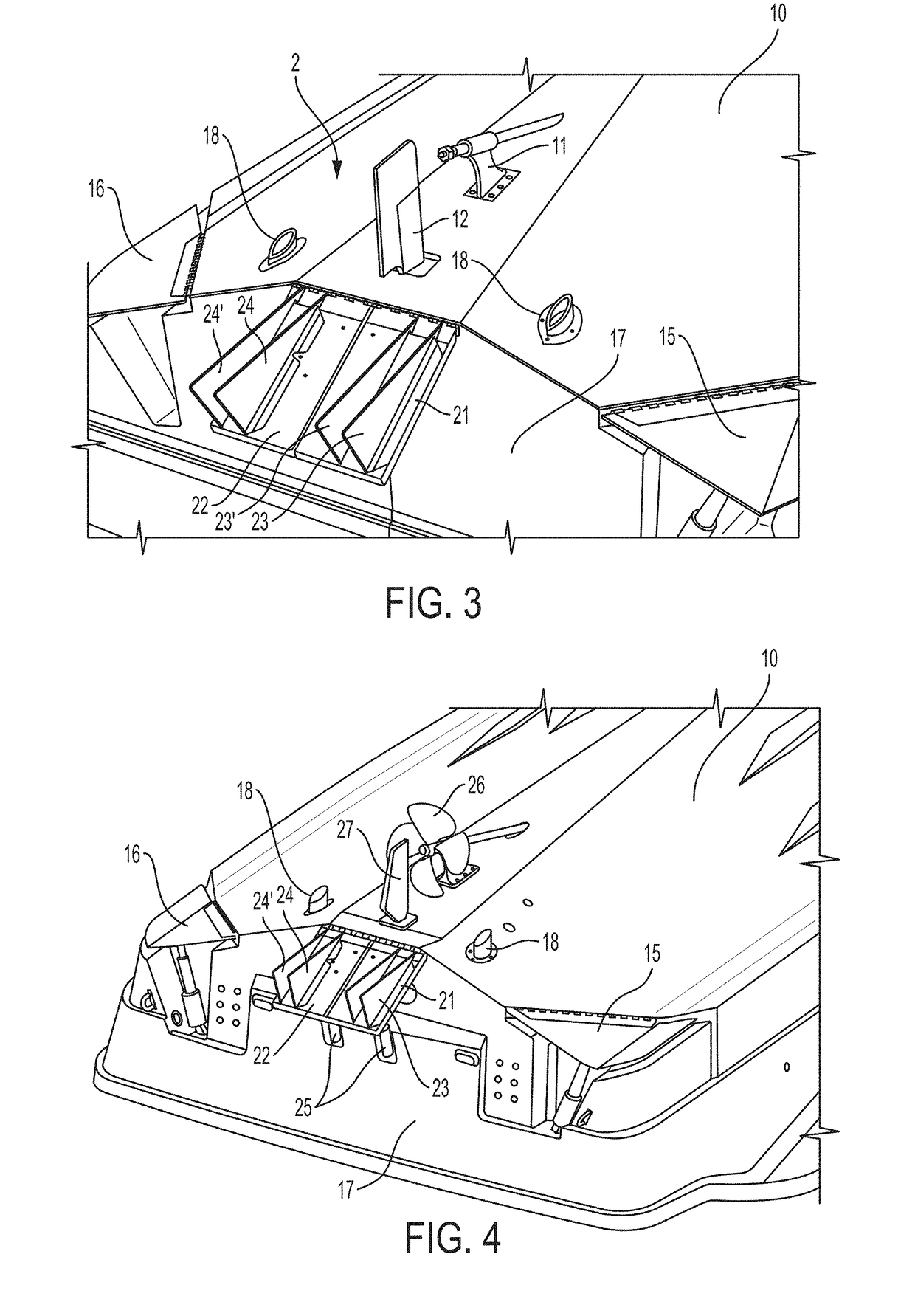
[0038]With reference to FIG. 1, shown is one embodiment the wake control system 1 installed on the hull 10 of an exemplary vessel. Shown is a conventional drive shaft and strut 11 disposed forward of a conventional rudder 12. A propeller (shown hereinafter) would be mounted to the drive shaft as typical for an inboard motor vessel. Disposed aft of the rudder generally about the centerline of the hull 10 is a wake control fin 13. In some embodiments, the fin 13 is vertically oriented and extends away from the hull 10 (downward when the hull 10 is on water). Fin 13 is slidingly mounted to a fin base 14 that provides an engagement point for the adjustability of the fin 13. Accordingly, fin 13 is attached to the fin base 14 such that the fin can change positions and be adjusted transversely across the width of the hull 10. In some embodiments, the fin 13 is slidingly engaged with the fin base 14 by a translation means such as a track, guide, rail, or the like that may be manually or aut...
PUM
 Abstract
Description
Claims
Application Information
 - R&D
- Intellectual Property
- Life Sciences
- Materials
- Tech Scout
- Unparalleled Data Quality
- Higher Quality Content
- 60% Fewer Hallucinations
Browse by: Latest US Patents, China's latest patents, Technical Efficacy Thesaurus, Application Domain, Technology Topic, Popular Technical Reports.
© 2025 PatSnap. All rights reserved.Legal|Privacy policy|Modern Slavery Act Transparency Statement|Sitemap|About US| Contact US: help@patsnap.com


