
Integrated bow thrusters

a bow thruster and integrated technology, applied in the field of bow thrusters for marine vessels, can solve the problems of process interference with proprietary technology, inefficient, costly and time-consuming, and interfere with the structural integrity of the vessel

Active Publication Date: 2010-08-03
BOSTON WHALER
View PDF12 Cites 8 Cited by
  • Summary
  • Abstract
  • Description
  • Claims
  • Application Information

AI Technical Summary

Benefits of technology

[0012]Unique procedures are utilized to complete the installation process, including alignment and guide tools, securing the structural components and installing the keystone insert. Because the integrity of the hull is not breached, and a superior design is utilized for the thruster motor supports, an enhanced system is achieved in manufacturing and performance, as well as eliminating undesired vibration, noise and maintenance.
[0013]This invention provides a clean and clever solution to the problems set forth above, is seamless in terms of integrating the system into conventional boat construction and manufacturing techniques with minimal valiance, is financially sound, and easy to service.
[0014]In accordance with the instant inventions, it an object thereof to provide an improved method and apparatus for installing bow thrusters into marine vessel hulls, which eliminates the process of cutting the hulls, drilling cavities within the hull or hull core, or otherwise modifying the hull to accommodate separate or auxiliary components for thruster installation.
[0015]It is a further object of the instant invention to provide an improved method and apparatus for installing bow thrusters into marine vessel hulls which incorporates a superior mechanical and electromechanical design, is operationally efficient, and is easy to maintain.
[0016]It is a further object of the instant invention to provide an improved method and apparatus for installing bow thrusters into marine vessel hulls which is cost-effective and of a superior manufacturing design.
[0017]A further object of the present invention is to provide an improved method and apparatus for manufacturing and installing bow thrusters into marine vessel hulls which includes all of the above mentioned features and objects to provide a substantially superior design, eliminating the problems encountered by prior methods and devices, and generally solving problems associated with incorporating bow or stern thrusters into hull without interfering with the primary hull design, function or materials.

Problems solved by technology

Such a process interferes with the structural integrity of the vessel, is inefficient, costly and time consuming.
Additionally, this process can interfere with proprietary technology and methods for manufacturing boat hulls, such as that disclosed in Applicants' U.S. Pat. No. 6,726,865, Entitled COMPOSITE MATERIAL FOR VEHICLE HULLS AND HULL MOLDING PROCESS.
There is significant labor associated with the glass work and finish work associated with this type of conventional hull modification and thruster installation.
It is very incompatible and unfriendly to the manufacturing environment due to the various multiple skill sets that need to be involved in the installation process to compensate for the separate requirements for subsequent modification of the hulls.
This is a convoluted mechanical and structural design and method of manufacture, and impractical by current standards.

Method used


Image

  • Integrated bow thrusters
  • Integrated bow thrusters
  • Integrated bow thrusters

Examples


Embodiment Construction

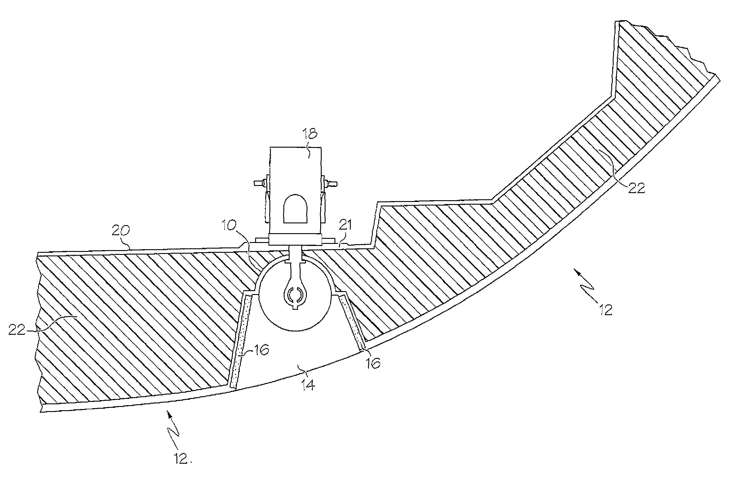
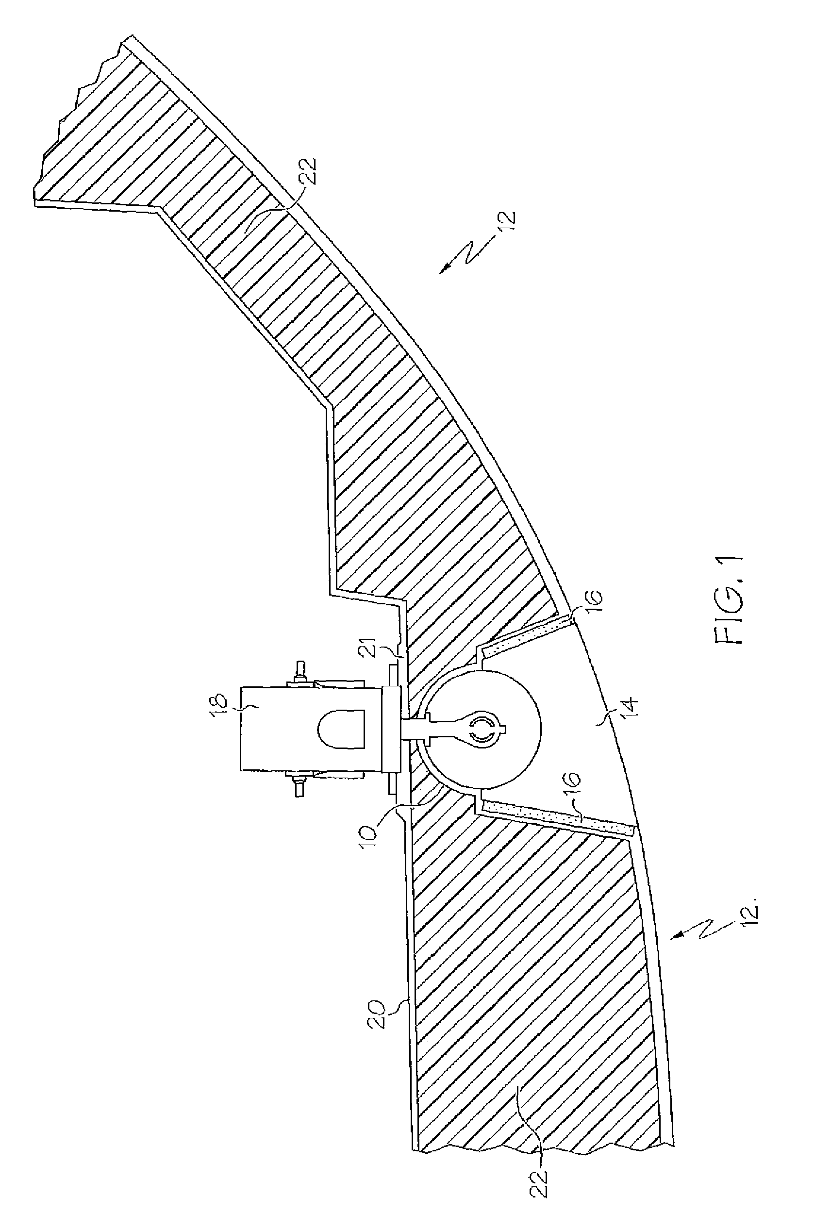
[0036]FIG. 1 shows a cross-sectional view of the hull and bow thruster installation. Although depicted in the bow area, it is understood that fore, mid-section, and / or aft thrusters can be utilized in vessel hulls at any location utilizing the technology and manufacturing methods described herein. The top of the bow thruster tunnel 10, and the area for insertion of the keystone insert, are integrally molded into the hull bottom 12 of a boat hull during the original manufacturing process. That is, no subsequent cutting, drilling of holes or cavities, or modification of the hull is required to accommodate the installation of the thruster or propeller assemblies as hereinafter described. A separate keystone insert 14 mates with the molded hull tunnel section and is bonded to the hull using bond lines 16 on opposite sides. Keystone insert 14 is bonded to the bottom half of the tunnel section 10 and completes the thruster propeller tunnel channeling water flow about the thruster propelle...


PUM


Abstract

A system and apparatus for providing integrated boat thrusters which eliminates interfering with the integrity of the hull, and undesirable drilling and cutting of the hull to accommodate separate glass tubes or pipes that are conventionally used to form thruster tunnels. The instant system provides integrally molded thruster tunnel sections within the hull, and unique keystone inserts which are complementary to the molded thruster tunnel sections and complete the water flow chambers through the hull about the propellers. Separate tubes are not utilized. Thruster motors and mounting mechanisms are securely fastened in flat planes enhancing strength, performance and maintenance of the assemblies. In a preferred embodiment, the keystone insert is generally wedge shaped to provide a secure fit and bond within the molded tunnel section having angled walls.

Description

BACKGROUND OF THE INVENTION[0001]1. Field of the Invention[0002]The inventions disclosed herein relate generally to bow thrusters for marine vessels, and more particularly to novel methods and apparatus for incorporating bow thruster tunnels, motors and related equipment into boat hulls during the manufacturing process. The instant inventions eliminate the need and use of conventional glass tubes for such a process and the undesirable modifications to standard hulls through drilling and cutting of hull, as well as provide superior structural support for the thruster electrical and mechanical components.[0003]2. Description of Related Art[0004]Typical bow thruster installations require relatively large holes to be drilled through the hull, after the hulls original manufacture, and thereafter fiberglass tubes to be glassed in and finished to commercial standards. Such a process interferes with the structural integrity of the vessel, is inefficient, costly and time consuming. Additiona...

Claims


Application Information

Patent Timeline
Patent Type & Authority Patents(United States)
IPC IPC(8): B63H25/46B63H5/16
CPCB63H25/46
Inventor BERMAN, RONALD M.RANIERI, KEITH P.
Owner BOSTON WHALER
Learn More