Method and apparatus for selectively altering a television video signal in real-time

a real-time, television video technology, applied in the direction of selective content distribution, signal generators with optical-mechanical scanning, television systems, etc., can solve the problems of not operating in real-time during a received broadcast, system not operating in real-time to detect commercial advertisements within a received broadcast signal, and insufficiently effective and economical systems that automatically operate in real-time for muting

Inactive Publication Date: 2004-08-03
TELEVENTIONS
View PDF51 Cites 223 Cited by
  • Summary
  • Abstract
  • Description
  • Claims
  • Application Information

AI Technical Summary

Problems solved by technology

Although a wide variety of techniques have been developed for detecting selected segments of television signals, heretofore there have been no sufficiently effective and economical systems that automatically operate in real-time for muting the television signal during the selected segments or for similar purposes.
Although the systems of U.S. Pat. Nos. 5,333,091 and 5,455,630 and PCT application PCT/US94/00223 are very effective in skipping over commercial advertisements and other unwanted broadcast material during the playback of a recorded broadcast program on a videotape, the systems do not operate in real-time during a received broadcast.
However, the system does not operate in real-time to detect commercial advertisements within a received broadcast signal.
Commercial advertisements may each be one minute or perhaps more in length thereby requiring a significant amount of storage for temporarily storing portions of the broadcast signal and thereby requiring a system which is not sufficiently economical for most purposes.
As with the previously described system, the systems of U.S. Pat. Nos. 4,750,052 and 4,782,401 do not operate in real-time and are not sufficiently econ

Method used


Image

  • Method and apparatus for selectively altering a television video signal in real-time
  • Method and apparatus for selectively altering a television video signal in real-time
  • Method and apparatus for selectively altering a television video signal in real-time

Examples


Embodiment Construction

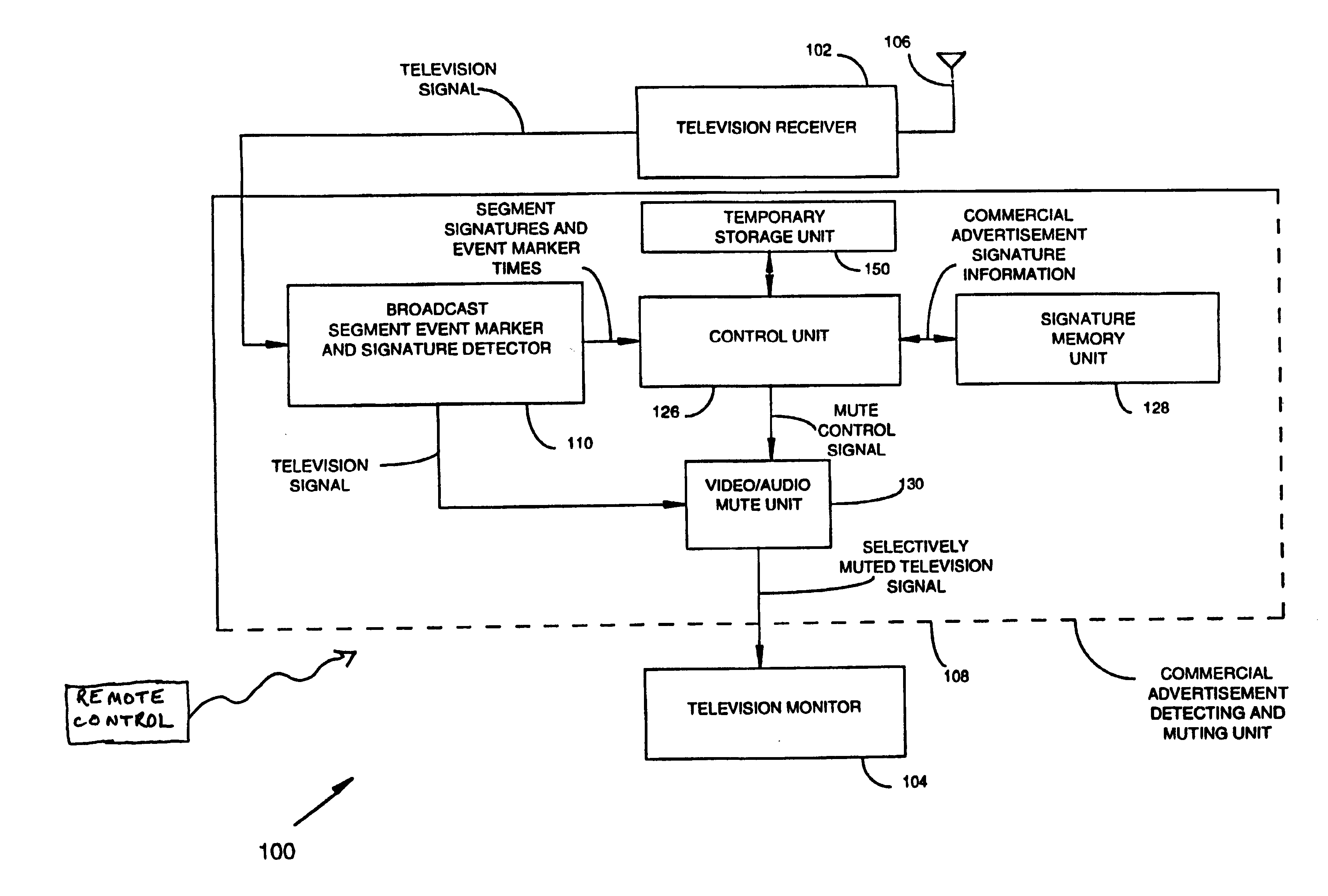
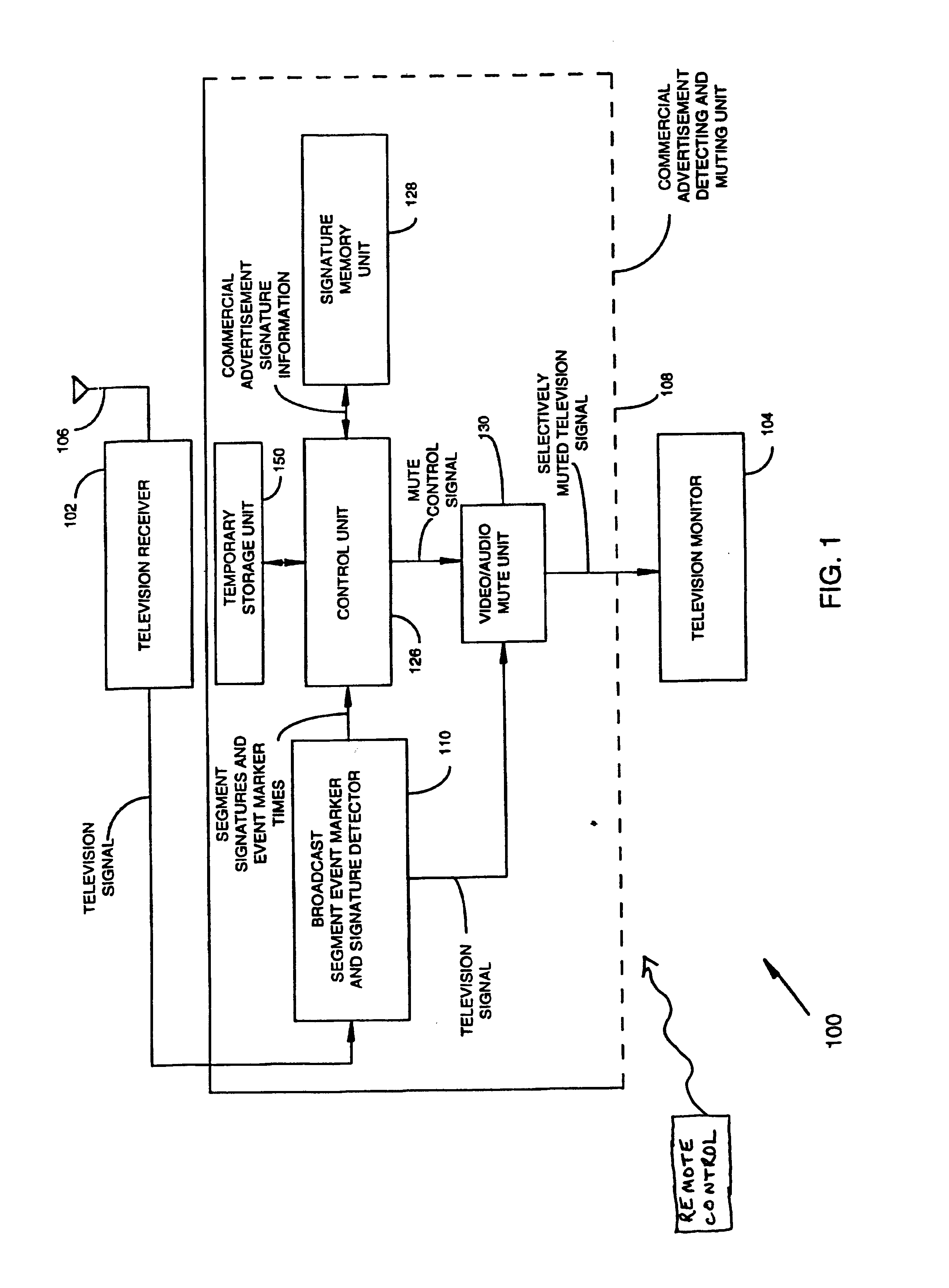
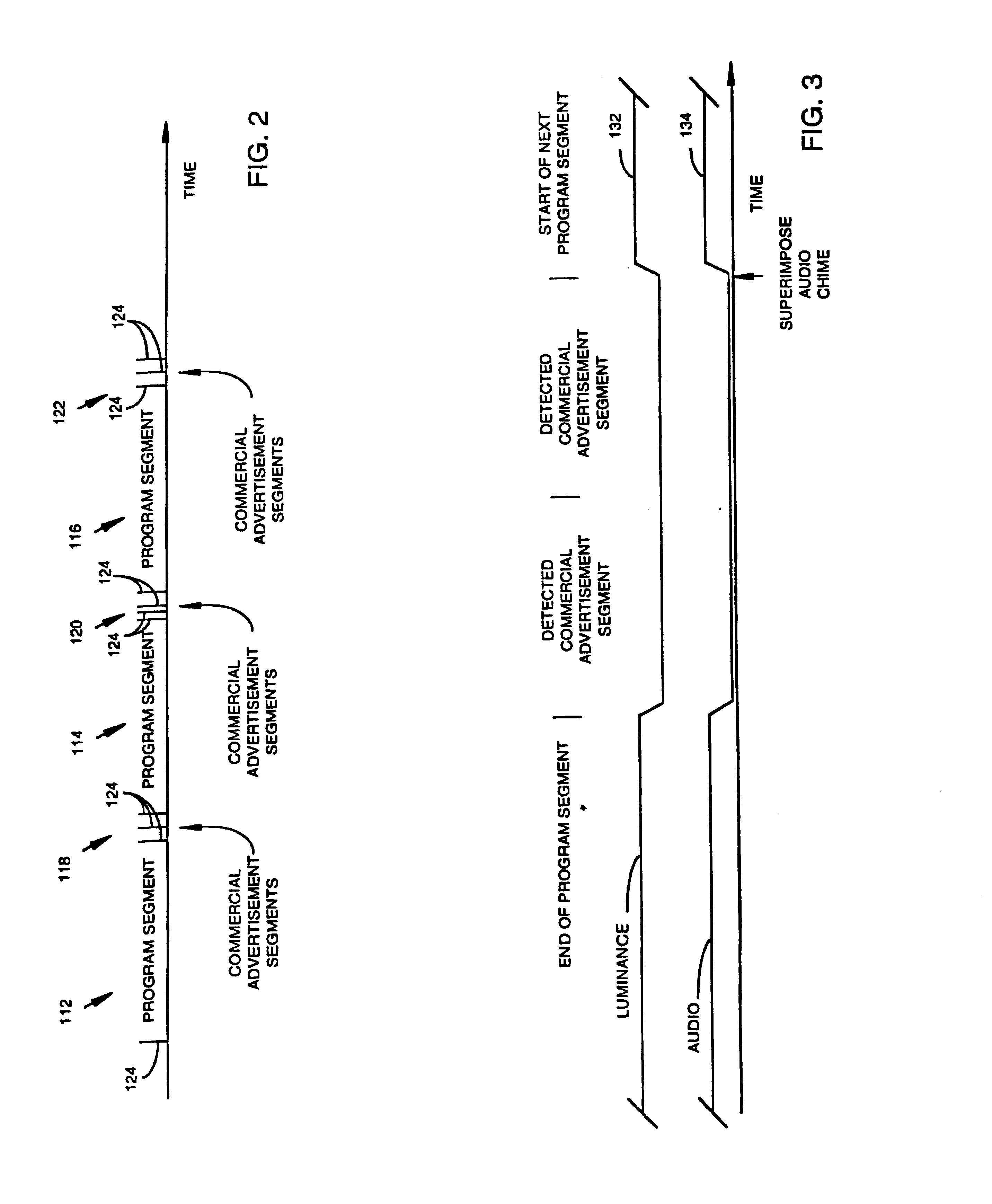
Referring to the Figures, exemplary embodiments of the invention are described for use with a television set for detecting "unwanted segments", such as commercial advertisements, in a television broadcast signal. Unwanted segments may also include other segments designated by a viewer, such as segments that may be deemed by a parent to be inappropriate for viewing by children. Upon detection of an unwanted segment, the audio and video components of the received broadcast signal may be muted. Alternatively, a secondary signal source may be substituted for viewing during the unwanted segment. Initially, an overview is provided with reference to the block diagrams and timing diagrams of FIGS. 1-7. Then, further details of particular implementations are provided with reference to the flowcharts and block diagrams of FIGS. 8-19.

FIG. 1 illustrates a television set 100 having a receiver 102 and a monitor 104. Television receiver 102, which includes a television tuner, receives an input bro...


PUM


Abstract

The method and apparatus operates in a television receiver to identify unwanted broadcast segments, such as commercial advertisements, of a television signal in real-time for the purpose of selectively altering the television display during each unwanted segment. A signature pattern associated with each segment of the television signal is detected and compared to stored signature patterns representative of selected segments such as commercial advertisement segments. If the signature pattern matches one of the stored signature patterns, the segment is thereby immediately identified as being one of the selected segments and is processed in real-time to mute or otherwise alter the television signal during the segment. If the signature pattern of the segment does not match any of the stored signature patterns, the segment is analyzed to determine whether the segment is nevertheless a selected segment and, if so, its signature pattern is stored along with the stored signature patterns.

Description

1. Field of the InventionThe invention relates to television signal processing systems and in particular to television signal processing systems for detecting selected segments of a television signal such as commercial advertisement segments.2. Description of Related ArtIt has long been a desire of many television viewers to have a system which automatically detects selected segments of a television signal such as commercial advertisements or other unwanted broadcast segments in real-time during a television broadcast for the purposes of, for example, muting the audio portion of the television broadcast during the unwanted broadcast material. Although a wide variety of techniques have been developed for detecting selected segments of television signals, heretofore there have been no sufficiently effective and economical systems that automatically operate in real-time for muting the television signal during the selected segments or for similar purposes.Examples of broadcast segment d...

Claims


Application Information

Patent Timeline
IPC IPC(8): H04N5/44H04N5/782
CPCH04N5/44H04N5/782H04N21/4316H04N21/4331H04N21/4332H04N21/8456H04N21/4396H04N21/44008H04N21/4622H04N21/812H04N21/4263H04N21/8455H04N21/4383
Inventor IGGULDEN, JERRY
Owner TELEVENTIONS
Why Eureka
Try Eureka