Ion thruster grid clear

a technology of ion propulsion and grid, which is applied in the direction of marine propulsion, machine/engine, vessel construction, etc., can solve the problems of narrow ion propulsion application range, low thrust of ion propulsion system when compared with chemical propulsion system, and relatively recent reduction to practical applications

Inactive Publication Date: 2004-09-07
L 3 COMM ELECTRON TECH
View PDF8 Cites 24 Cited by
  • Summary
  • Abstract
  • Description
  • Claims
  • Application Information

AI Technical Summary

Problems solved by technology

Although the principle of ion propulsion was established many decades ago, it has only relatively recently been reduced to practical applications.
Unfortunately, the range of ion propulsion applications is narrowed by the fact that, although they are efficient, ion propulsion systems develop very low thrust when compared with chemical propulsion systems.
Over time, these deposits can grow large enough to flake off and cause a short between the grids, shutting down the thruster.
Consequently, the amount of energy that can be delivered to very low or very high resistance shorts is limited, making these shorts particularly difficult to clear.
If the timing is too long the thruster hardware will be damaged, and if the timing is too short, the grid clear will not be effective.
However, the only short ever experienced on this mission was cleared through natural thermal cycling, and not by use of the grid clear circuitry.
Consequently, the grid clear has never been attempted.

Method used


Image

  • Ion thruster grid clear
  • Ion thruster grid clear
  • Ion thruster grid clear

Examples


Embodiment Construction

In the following description, reference is made to the accompanying drawings which form a part hereof, and which is shown, by way of illustration, several embodiments of the present invention. It is understood that other embodiments may be utilized and structural changes may be made without departing from the scope of the present invention.

1.0 Overview

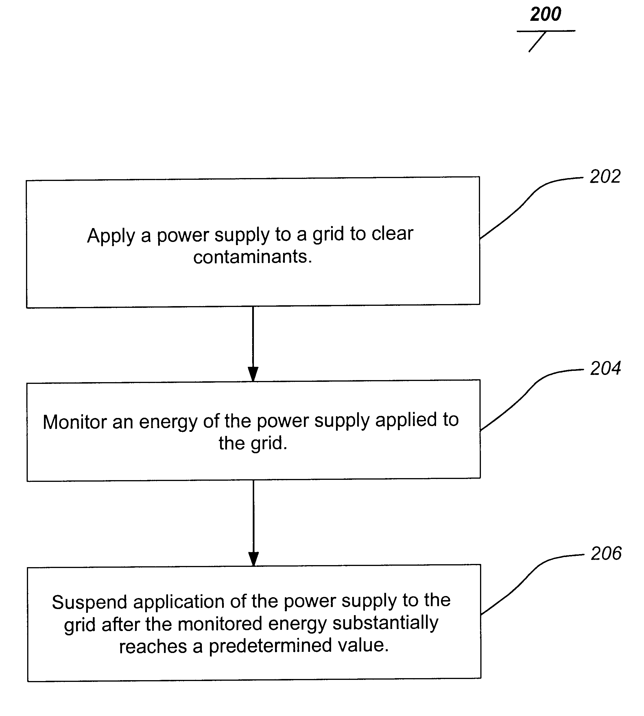
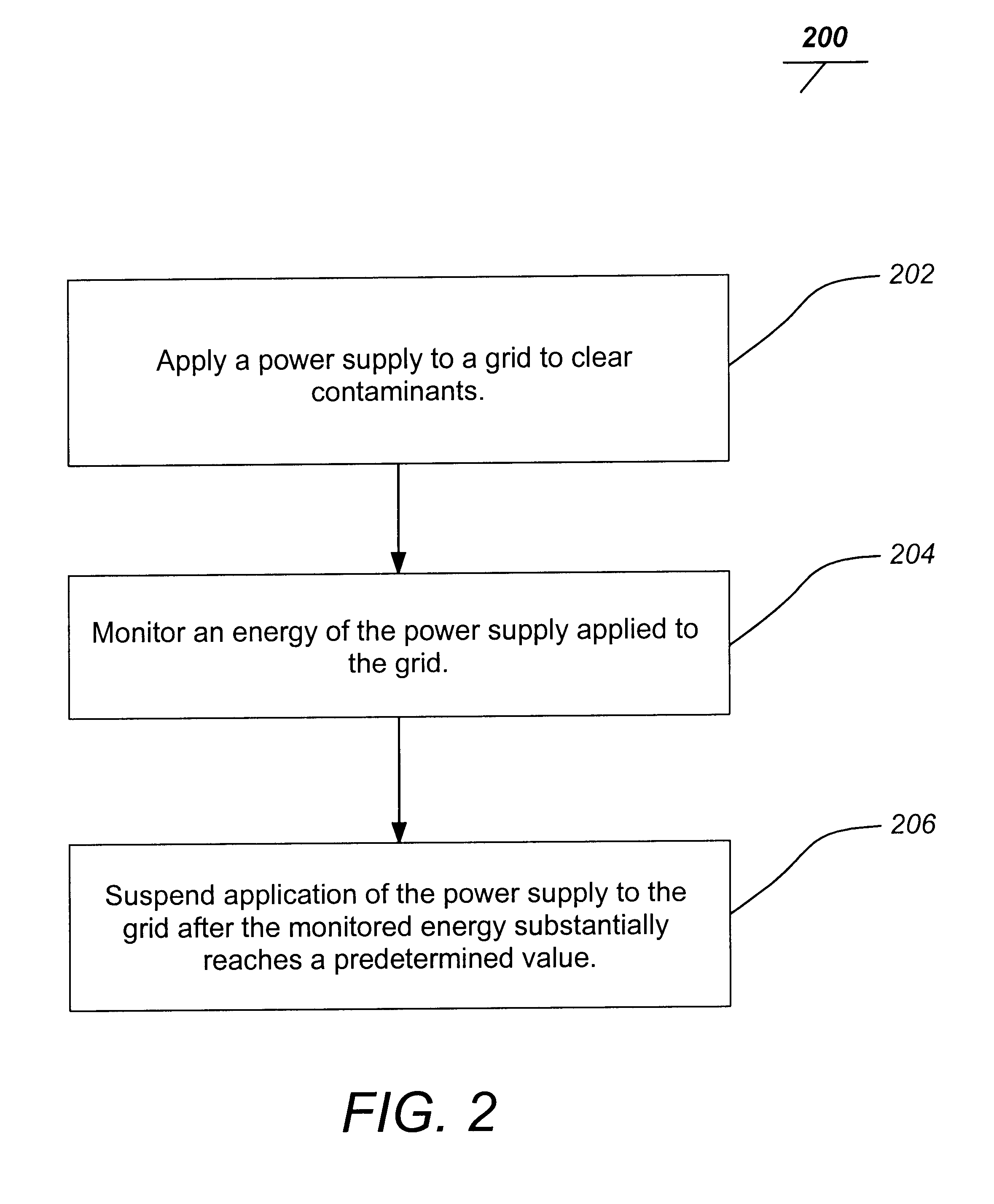
In general, embodiments of the invention involve a controlled application of a power supply to the contaminated grids of an ion thruster to bum off the residue. The power supply is designed as a constant current source. The product of the current applied from the power supply and the applied duration are limited to a preset value. Thus, the total energy delivered to clear the short is regulated. In addition, the output voltage of the power supply is limited to a predetermined value to prevent damage to the thruster and the associated hardware.

Embodiments of the invention enable much larger energies to be delivered to a thruster grid sh...


PUM


Abstract

The invention discloses a method and device for clearing an ion thruster grid of contaminants. A typical method includes applying a power supply to a grid to clear contaminants, monitoring an energy applied to the grid of the applied power supply and suspending application of the power supply to the grid after the monitored energy substantially reaches a predetermined value. A typical device includes a controller for applying a power supply to a grid to clear the grid of contaminants and a timer for monitoring an energy applied to the grid of the applied power supply and suspending application of the power supply to the grid after the monitored energy substantially reaches a predetermined value.

Description

1. Field of the InventionThe present invention relates to field driven ion propulsion systems, and particularly to methods for maintaining operation of such propulsion systems.2. Description of the Related ArtAlthough the principle of ion propulsion was established many decades ago, it has only relatively recently been reduced to practical applications. Ion propulsion generally involves employing an ionized gas accelerated electrically across charged grids to develop thrust. The electrically accelerated particles can achieve speeds of approximately 30 km / second. The gas used is typically a noble gas, such as xenon. The principal advantage afforded by ion propulsion systems over conventional chemical propulsion systems is their very high efficiency. For example, with the same amount of fuel mass an ion propulsion system can achieve a final velocity as much as ten times higher than that obtainable with a chemical propulsion system.Unfortunately, the range of ion propulsion application...

Claims


Application Information

Patent Timeline
Patent Type & Authority Patents(United States)
IPC IPC(8): F03H1/00
CPCF03H1/0043H01J2237/335
Inventor STICKELMAIER, JOHN F.
Owner L 3 COMM ELECTRON TECH
Why Eureka
Try Eureka