Pneumatic tire including twisted sipe

a technology of pneumatic tires and sipes, applied in the field of pneumatic tires, can solve the problems of small blocks not being able to contact adjacent small blocks with sufficient force, and affecting the performance of pneumatic tires

Inactive Publication Date: 2004-09-07
BRIDGESTONE CORP
View PDF22 Cites 17 Cited by
  • Summary
  • Abstract
  • Description
  • Claims
  • Application Information

AI Technical Summary

Problems solved by technology

When the degree of leaning becomes large, a contact patch area area of the contact patch area decreases, so that there is a possibility that the performance on ice and snow may deteriorate.
However, if the sipes are formed straight in the sipe depth direction, deformation of the small blocks due to ground contact is not capable enough of causing the small blocks to contact the adjacent small blocks with sufficient force.
Accordingly, leaning suppression is weak and thus it can hardly be said that contact patch area area of the contact patch area is sufficiently ensured.
Thus, there has been a problem in that when a vehicle on which the pneumatic tires are actually fitted is driven, the steel cords provided in the reinforcing layer closest to the tread surface side lean toward the tire circumferential direction, thereby generating a force to restore the tire distorted by ground contact pressure to the original shape (Self Alignment Torque, referred to as SAT hereinafter).

Method used


Image

  • Pneumatic tire including twisted sipe
  • Pneumatic tire including twisted sipe
  • Pneumatic tire including twisted sipe

Examples


first embodiment

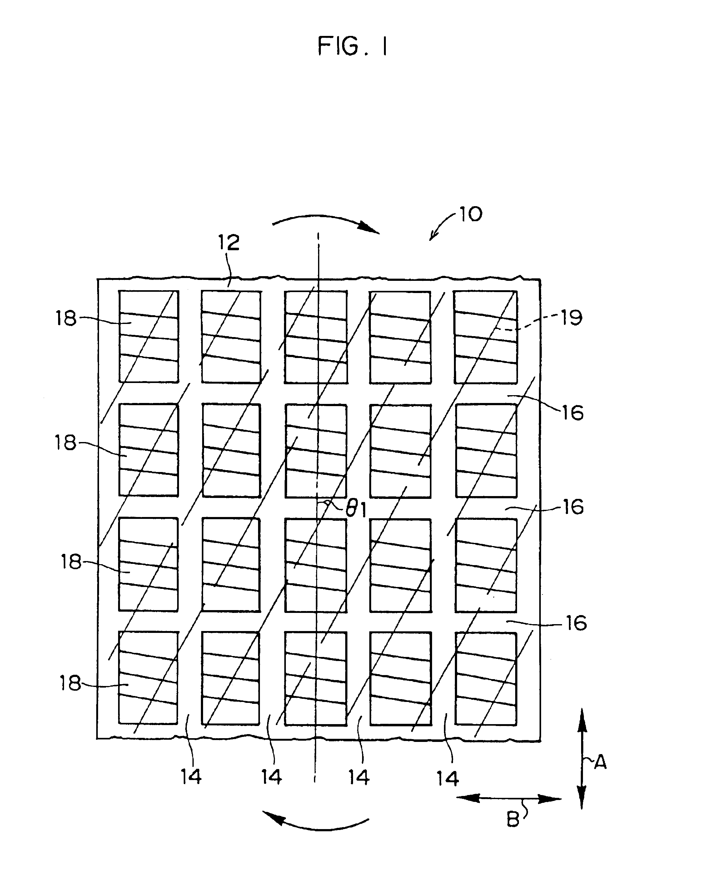
A pneumatic tire relating to a first embodiment of the present invention will be described in accordance with FIG. 1 through FIG. 4.

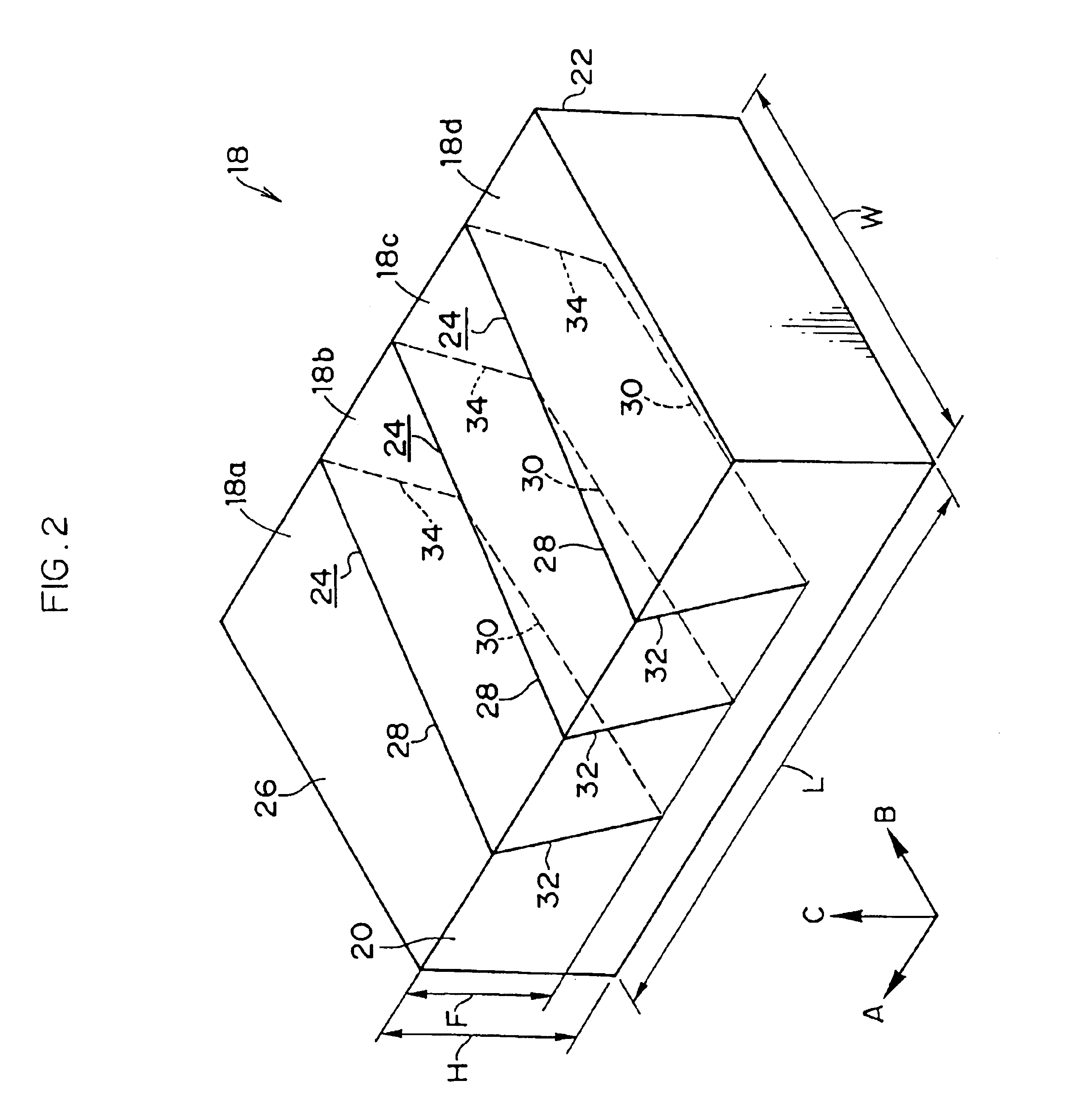
As illustrated in FIG. 1, in a tread 12 of a pneumatic tire 10 of the present embodiment, a plurality of blocks 18 are formed. The blocks 18 are demarcated by main grooves 14, which extend along the tire circumferential direction (the direction indicated by arrow A, and referred to as the A direction hereinafter), and by lug grooves 16, which extend along the tire transverse direction (the direction indicated by arrow B, and referred to as the B direction hereinafter).

Reinforcing layers in which steel cords 19 are inclined at a predetermined angle with respect to an A direction are laminated under the tread 12 in order to ensure stiffness of the pneumatic tire 10. In the outermost reinforcing layer closest to the tread 12 surface, the steel cords 19 are disposed parallel to each other and inclined at a predetermined angle .theta.1 with respect to the A ...

second embodiment

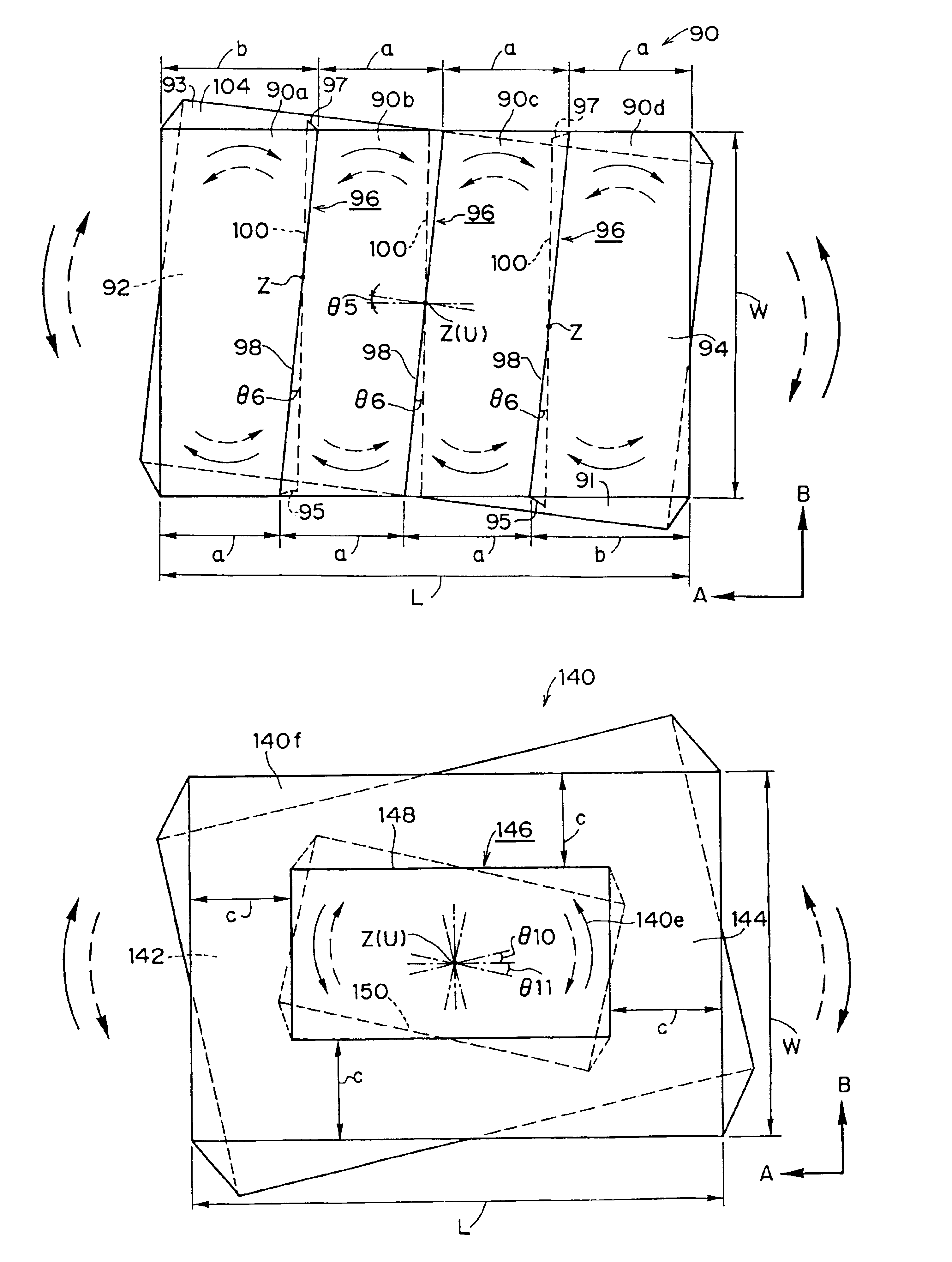
Next, a pneumatic tire relating to a second embodiment of the present invention will be described in accordance with FIGS. 5 and 6. Since the only difference between the pneumatic tire of the first embodiment and that of the present embodiment is the shape of sipes, only a sipe and a blade which is used to form the sipe will be described. The same reference numerals are used to designate elements which are the same as those in the first embodiment, and detailed description thereof will be omitted.

First, the shape of a blade which forms a sipe will be described in accordance with FIG. 6. A blade 40 is formed with such a shape that protruding portions 42, which are triangular with a height of 0.5 K in a D directional section, are formed in a zigzag, i.e., protruding alternately on the both sides of a virtual central plane V with intervals J. Each protruding portion 42 extends in the E direction which is perpendicular to the D direction. The blade 40 formed in such a manner is placed s...

third embodiment

Next, a pneumatic tire relating to a third embodiment of the present invention will be described in accordance with FIG. 7 and FIG. 8. Since the only difference between the pneumatic tires of the first and second embodiments and that of the present embodiment is the shape of sipes, only a sipe and a blade which is used to form the sipe will be described. The same reference numerals are used to designate elements which are the same as those in the first and second embodiments, and detailed description thereof will be omitted.

First, the shape of a blade which forms a sipe will be described in accordance with FIG. 8. A blade 50 is formed with such a shape that protruding portions 52, which are triangular with a height of 0.5 L in an E directional section, are formed in a zigzag, i.e., protruding alternately on the both sides of a virtual central plane V with intervals M. Each protruding portion 52 extends in the D direction which is perpendicular to the E direction. The blade 50 with s...


PUM


Abstract

A pneumatic tire.In a block 18 formed on a tread surface, a sipe 24 which is twisted at a predetermined angle from a surface portion 28 toward a bottom portion 30 is provided. Due to ground contact pressure exerted on a contact patch area 26, small blocks 18a to 18d rotate, so that adjacent small blocks abut each other with a strong force. As a result, leaning of the small blocks 18a to 18d is suppressed, and a contact patch area area on the contact patch area 26 increases, so that performance on ice and snow improves. Moreover, due to rotation of the small blocks 18a to 18d, a torque (SAT) for restoring the small block to an original shape is generated, so that SAT generated by steel cords can be suppressed.

Description

The present invention relates to a pneumatic tire which exhibits an excellent performance on ice and snow.BACKGROUND TECHNOLOGYConventionally, a pneumatic tire which is provided with a plurality of blocks on a tread surface, wherein the blocks are defined by main grooves formed in the tire circumferential direction, lug grooves formed in the tire transverse direction and the like has existed. By providing blocks on a tread surface in such a manner, a pneumatic tire ensures favorable braking and traction force, steering stability and the like.Also, improvement in performance on ice and snow and a wet property has been attempted by providing sipes in the blocks to increase an edge length and to increase gripping force.Further, under the tread surface of the pneumatic tire formed in this way, reinforcing layers in which a number of steel cords are provided parallel to each other are laminated in order to strengthen stiffness of the tread.In the pneumatic tire structured as described ab...

Claims


Application Information

Patent Timeline
Patent Type & Authority Patents(United States)
IPC IPC(8): B60C11/12B60C11/11
CPCB60C11/11B60C11/12B60C11/1218B60C11/1222B60C2011/1213Y10S152/03Y10S152/902
Inventor KOIDE, MASAFUMI
Owner BRIDGESTONE CORP
Why Eureka
Try Eureka