

Instrumentation for stabilizing certain vertebrae of the spine
- Summary
- Abstract
- Description
- Claims
- Application Information
AI Technical Summary
Benefits of technology
Problems solved by technology
Method used
Image

Examples
Embodiment Construction
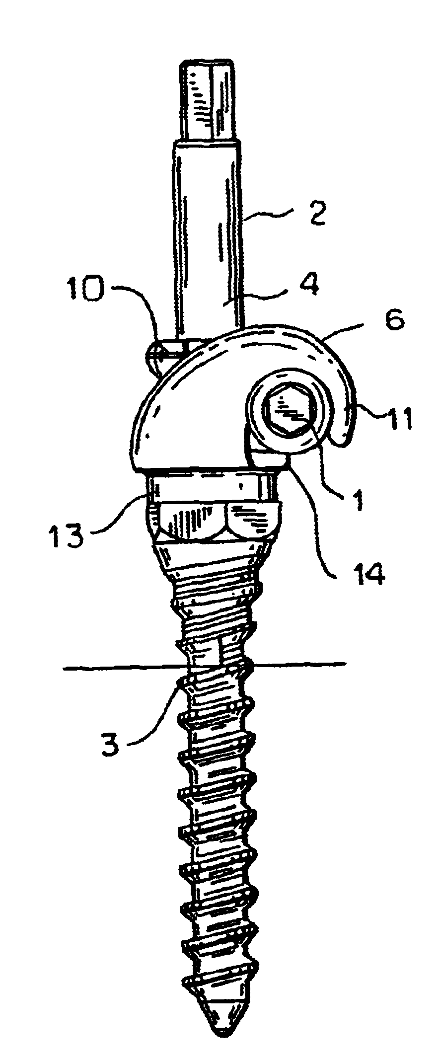
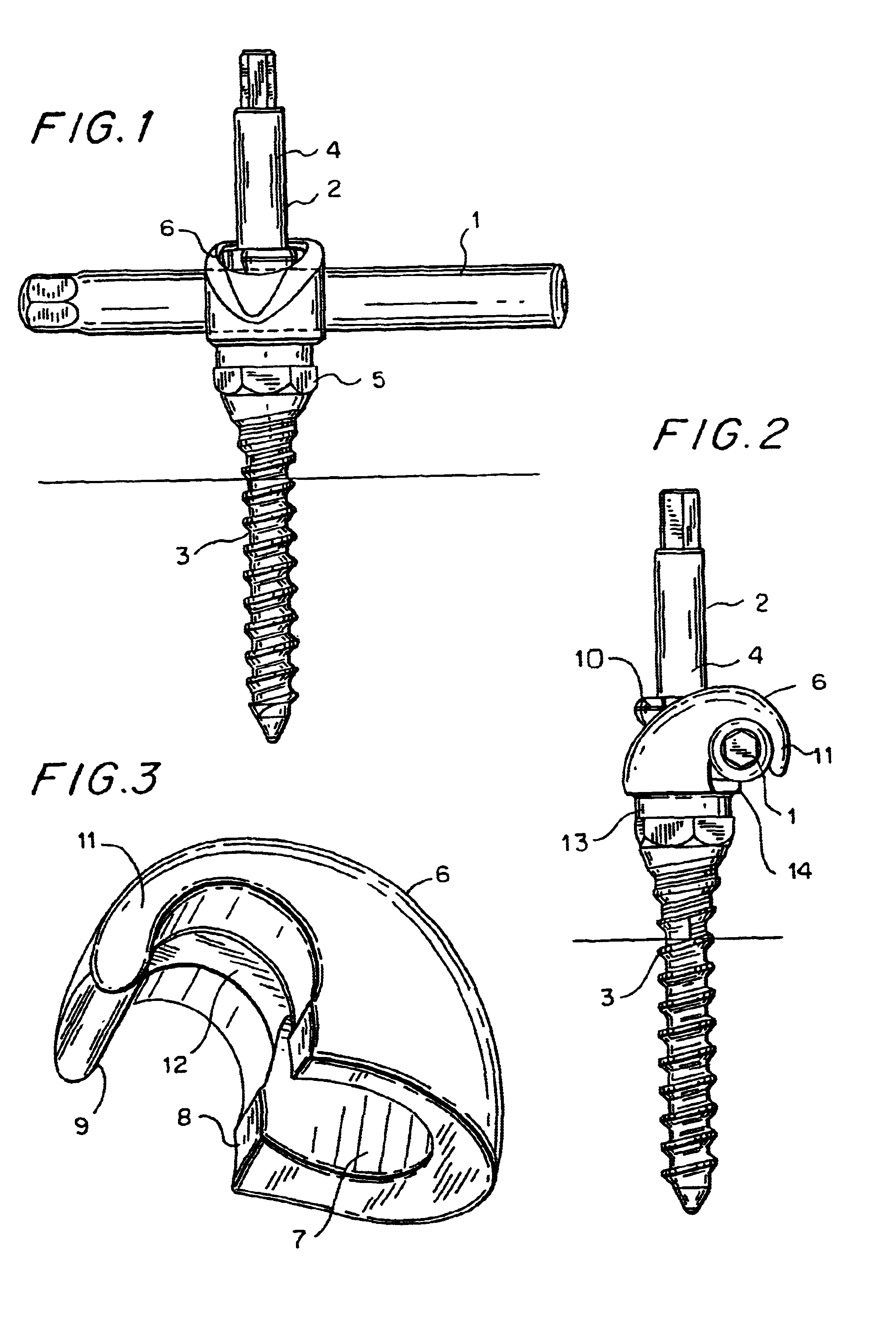
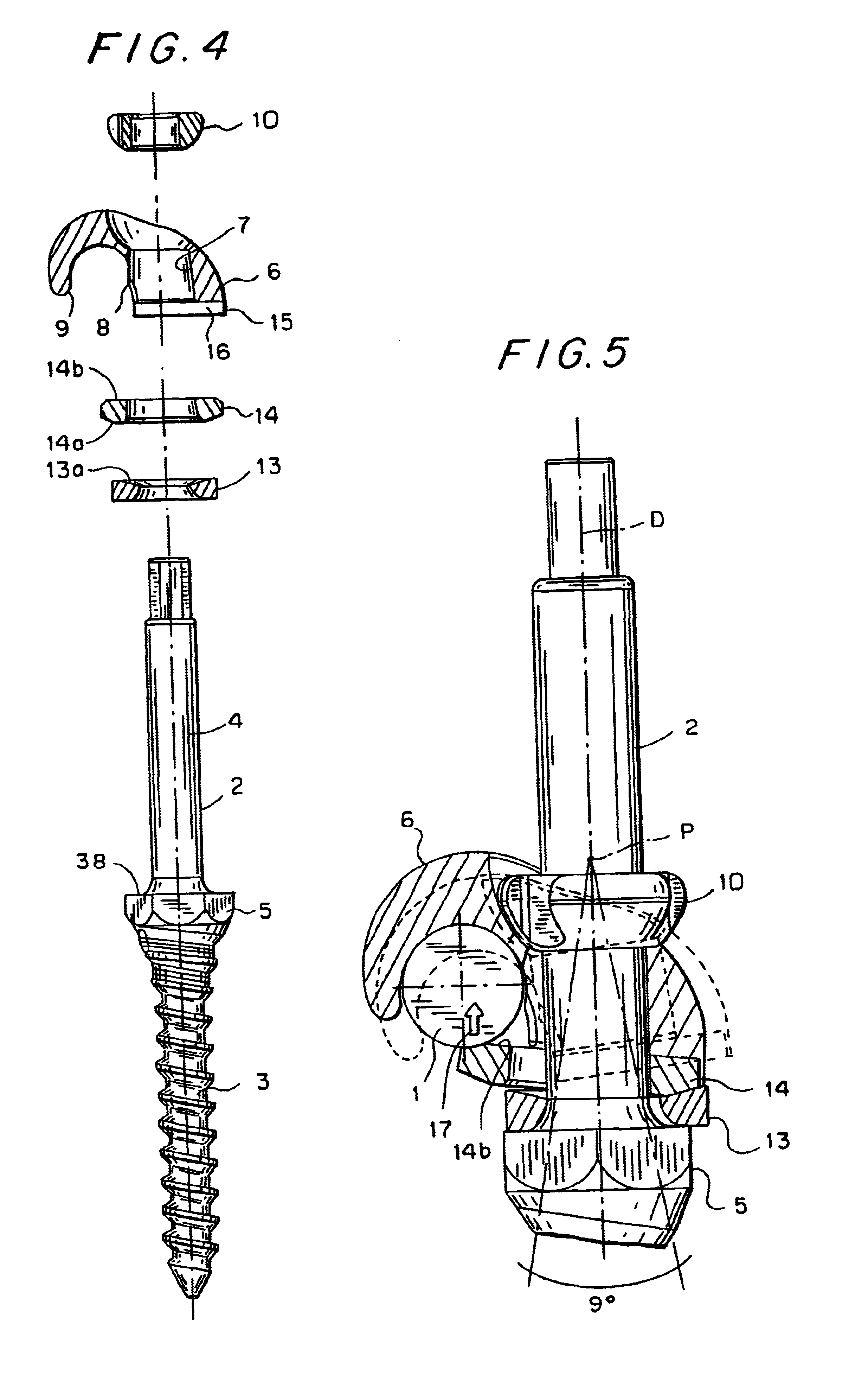
The instrumentation illustrated in FIGS. 1 to 5 comprises a pedicle screw 2, a nut 10, a connector 6, a upper slip washer 14 and a lower slip washer 13. The pedicle screw 2, from top to bottom (as viewed in FIGS. 1 and 2), consists of a threaded section 4, a curvilinear shoulder 38, a hexagonal nut 5 and a cancellous type thread section 3. The pedicle screw 2 is received by an opening 7 formed in the connector 6. The nut can be a break-away nut 63' as seen in FIGS. 14b to 18b. This nut 63' has a upper part 63'a (FIG. 15b) that is broken off after the nut 63' has been clamped as seen in FIG. 16b.
The connector 6 is comprised of a hook portion 11 having a recess to grasp a smooth round spinal stabilizing rod 1. The hook portion two opposing ridges 8 and 9, which have a distance to each other, which is shorter than the diameter of the rod 1. The two ridges 8 and 9 provide snap-on means when the rod 1 is moved into the recess.
The lower washer 13 is slipped over the thread section 4 and r...
PUM
 Abstract
Description
Claims
Application Information