Magnetic encoder and wheel bearing assembly using the same

a technology of magnetic encoder and wheel bearing, which is applied in the direction of mechanical equipment, instruments, transportation and packaging, etc., can solve the problems of increasing the load on the molding, affecting the quality of the finished product, and requiring a large number of processing steps

Inactive Publication Date: 2004-09-14
NTN CORP
View PDF14 Cites 36 Cited by
  • Summary
  • Abstract
  • Description
  • Claims
  • Application Information

AI Technical Summary

Benefits of technology

According to this aspect of the present invention, since the multi-pole magnet element is a sintered element in which a powdery mixture of the powdery magnetic material and the powdery non-magnetic metallic material is sintered, the following advantages can be obtained.
Where the first sealing plate is made of a generally inverted Z-shaped configuration as hereinbefore described, any one of the following structures can advantageously be employed.

Problems solved by technology

The molding of the coder made of the elastic material or the elastomer containing the powdery magnetic material or the magnetic particles, is performed by shaping with the use of a mold assembly appropriate to the shape of a product by means of, for example, an injection molding technique or a compressive molding technique and, in the case where a vulcanizing step is needed, the elastic material or the elastomer should be retained within the molding assembly for a vulcanizing time needed, thereby posing a problem in that a relatively large number of processing steps are needed.
In such case, when particulate matter such as sand particles are trapped in and bitten within a gap delimited between the bearing seal surface on a rotating side and a detecting sensor surface on a stationary side during run of a motor vehicle, it is often observed that the surface of the coder made of the elastic material or the elastomer will be damaged considerably due to, for example, frictional wear.
Also, when a preform material prepared by kneading a mixture of the powdery magnetic material or the magnetic particles and the plastomer or the elastic material according to the conventional manufacturing method is injected into or compressed within the mold assembly to form the coder, or is shaped by means of the insert molding technique to form the coder, since the magnetic particulate component contained in the preform material is an oxide of metal and is therefore so hard as to bring about a problem associated with frictional wear of molds of the mold assembly and / or the molding machine in term of mass productivity and since the preform material containing a high content of the magnetic particulate component tends to exhibit a high melt viscosity, there has been a problem in that the molding pressure or the mold clamping force has to be increased, resulting in increased load on the molding.
Even in the case of the extrude molding using the T-shaped die and the sheet molding such as the calendaring technique, since the magnetic particulate component contained in the preform material is an oxide of metal and is therefore hard, there has been a problem associated with frictional wear of the T-shaped die and rolls of the calendaring machine in terms of mass productivity.
On the other hand, if one or the both of the powdery magnetic material and the powdery non-magnetic metallic material has or have an average particle size greater than 150 .mu.m, the green compact will not have a sufficient strength.
%, the amount of the powdery non-magnetic metallic material acting as a metal binder will be so insufficient that the resultant multi-pole magnet element obtained after sintering will become rigid, but fragile.
It may occur that no green compact can be molded.
%, the amount of the powdery magnetic material will be relatively small and it will therefore be difficult to secure the magnetic force necessary to achieve a stabilized sensing.
For this reason, there is a possibility that the multi-pole magnet element may be damaged, making it difficult to secure fixing between the multi-pole magnet element and the core metal.
%, there is a high possibility that the green compact (the green compact) being prepared may break by the effect of a spring back phenomenon that will be induced as a result of an elastic restoration from an elastically deformed state of powdery mixture when the compacting or molding pressure applied is progressively removed.
%, the physical strength of the sintered element will be so low that it is difficult to mechanically fix the sintered element to the core metal by means of a clamping process or a press fitting process and, also, because of lack of a sufficient bondability among the particles, there is a possibility that the green compact cannot be molded.
However, if the plate thickness is smaller than 0.3 mm, the green compact is difficult to mold.
On the other hand, if the plate thickness is too large, variation in density will easily occur in the green compact to such an extent as to result in the green compact after having been sintered that is susceptible to deformation.
As is well known to those skilled in the art, the wheel bearing assembly is very often exposed to a severe environment on a road surface where particles such as, for example, sand particles tend to be trapped in between the magnetic encoder and the magnetic sensor facing the magnetic encoder.

Method used


Image

  • Magnetic encoder and wheel bearing assembly using the same
  • Magnetic encoder and wheel bearing assembly using the same
  • Magnetic encoder and wheel bearing assembly using the same

Examples


Embodiment Construction

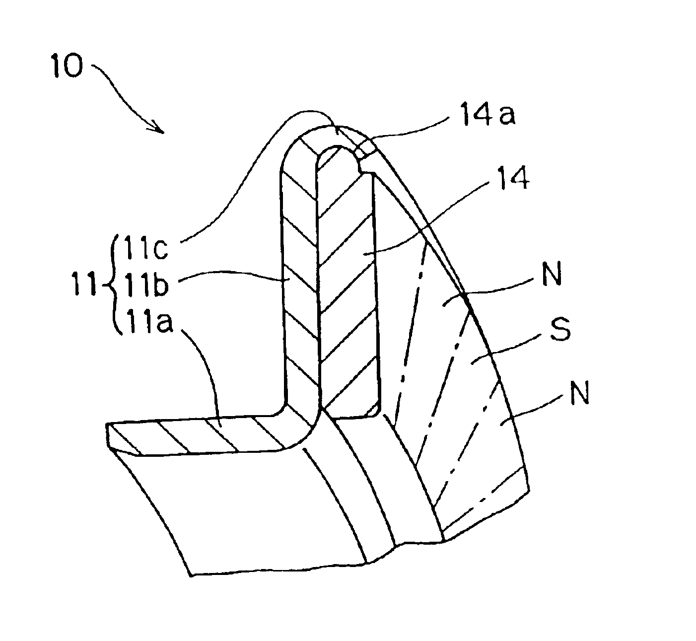
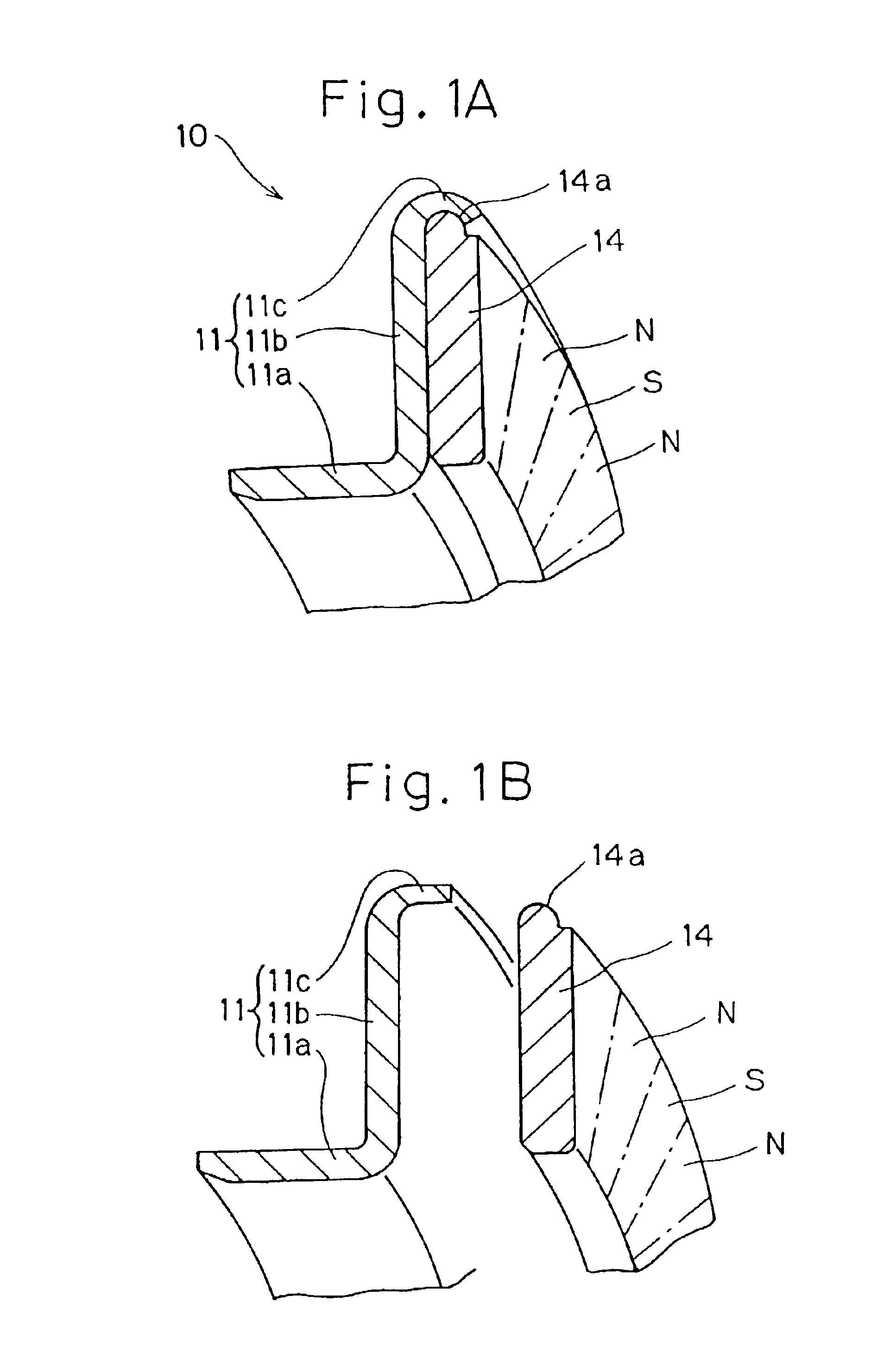
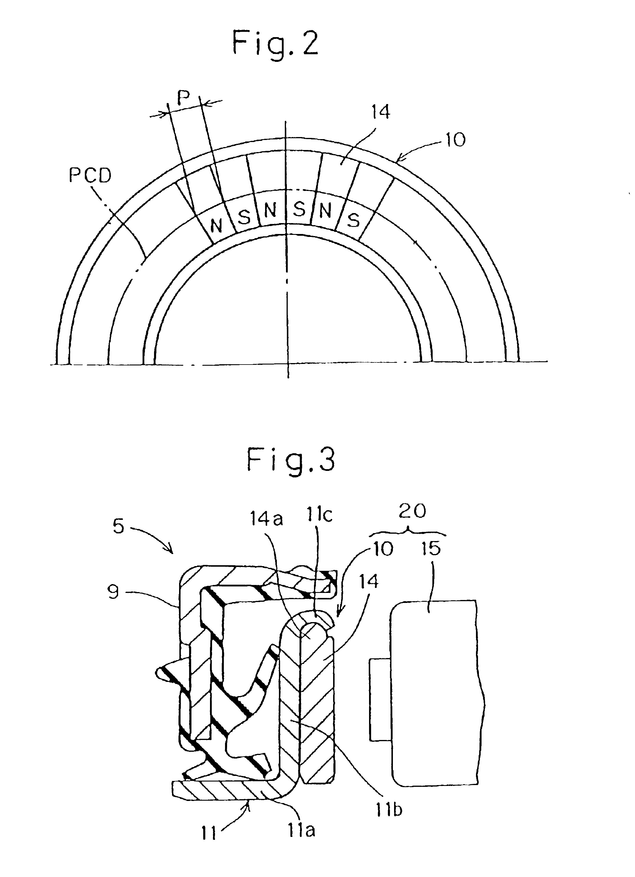
Referring to FIGS. 1 to 3 pertaining to a first preferred embodiment of the present invention, a magnetic encoder 10 shown therein includes an annular core metal 11 of a generally L-shaped section having a generally cylindrical axial wall 11a and a radial upright wall 11b substantially perpendicular to the axial wall 11a, and an annular multi-pole magnet element 14 secured to one of opposite annular surfaces of the radial upright wall 11b that faces towards a magnetic sensor 15. The multi-pole magnet element 14 has a plurality of opposite magnetic poles N and S defined therein so as to alternate with each other in a direction circumferentially thereof as best shown in FIG. 2, and is made up of a magnetic disc. The opposite magnetic poles S and N in the multi-pole magnet element 14 alternate with each other in the circumferential direction at intervals of a predetermined pitch p along the pitch circle diameter PCD shown in FIG. 2.

The magnetic encoder 10 of the structure described abo...


PUM

PropertyMeasurementUnit
particle sizeaaaaaaaaaa
thicknessaaaaaaaaaa

Abstract

To provide a magnetic encoder that has an increased detecting sensitivity, can be thin-walled, have an increased reliability and an increased durability, can easily be handled during manufacture and assembly and is excellent in productivity, the magnetic encoder (10) includes a multi-pole magnet element (14) having opposite magnetic poles alternating with each other in a circumferential direction, and a core metal (11) for supporting the multi-pole magnet element (14). The multi-pole magnet element (14) is made of a sintered element prepared by sintering a powdery mixture of a powdery magnetic material and a powdery non-magnetic metallic material.

Description

1. Field of the InventionThe present invention generally relates to a magnetic encoder used in, for example, a rotation detecting device for detecting the rotational speed of bearing elements rotatable relative to each other and a wheel bearing assembly utilizing such magnetic encoder. In particular, the present invention relates to the magnetic encoder that forms one of component parts of a bearing sealing device that can be mounted in the rotation detecting device employed in an anti-skid control system for a motor vehicle for detecting the rotational speed of front and rear vehicle wheels.2. Description of the Prior ArtThe rotation detecting device for use in association with an anti-skid control system generally used in, for example, motor vehicles has hitherto been available in various types. Of them, the rotation detecting device has been known which includes a toothed rotor and a rotation detecting sensor that are separated from each other by means of a sealing device used to...

Claims


Application Information

Patent Timeline
Patent Type & Authority Patents(United States)
IPC IPC(8): F16J15/32G01P3/487G01P3/44G01P3/42G01D5/12
CPCF16C33/7879F16C41/007F16J15/326G01P3/443G01P3/487F16C2326/02F16C19/184G01D5/12
Inventor NAKAJIMA, TATSUO
Owner NTN CORP
Why Eureka
Try Eureka