Tank cap

a technology of tank caps and spherical plates, applied in the field of tank caps, can solve the problems of hard on the ears and large noise, and achieve the effect of reducing operating noise during opening and closing and standing operability

Inactive Publication Date: 2004-09-21
TOYODA GOSEI CO LTD
View PDF12 Cites 17 Cited by
  • Summary
  • Abstract
  • Description
  • Claims
  • Application Information

AI Technical Summary

Benefits of technology

The object of the present invention is thus to provide a tank cap which can close a tank opening with a small value of rotating, has outstanding operability such as in regard to alignment for opening and closing, and also has reduced operating noise during opening and closing.
On the other hand, in the state where the tank cap has closed the tank opening, when the rotational torque is applied to the handle in the opening direction, the handle engagement element and torque piece engagement element go into the second non-engaged state to disengage by means of a smaller torque than with the first non-engaged state. That is, the rotating force in the closing direction returns the positional relationship between the handle engagement element and the torque piece engagement element to an initial position. Thus, when the tank cap is to be closed again, the positional relationship of the torque piece engagement element and handle engagement element is fixed and alignment for closing the tank opening is facilitated.
Since the elastic deformation direction of the elastic torque piece is a different direction for first non-engaged state and for second non-engaged state, the cap allows a greater degree of freedom. For example, the torque mechanism can be easily designed such that the elastic torque piece has the elastic deformation of second non-engaged state markedly smaller than that of the first non-engaged state.

Problems solved by technology

The rotational torque is particularly large when transitioning to the second non-engaged state, resulting in the problem of a large noise, which is hard on the ears, being caused by the operation.

Method used


Image

  • Tank cap
  • Tank cap
  • Tank cap

Examples


Embodiment Construction

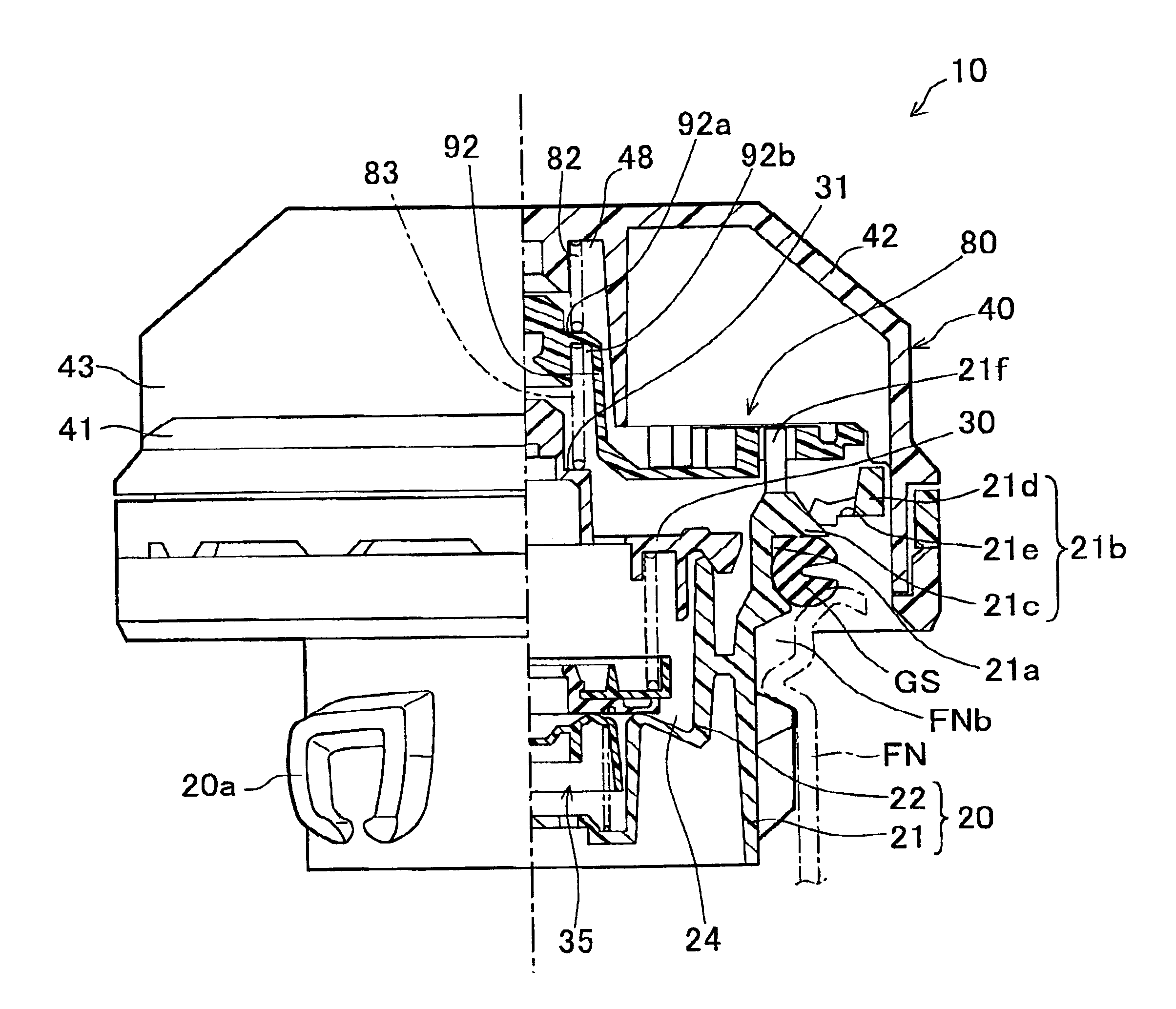
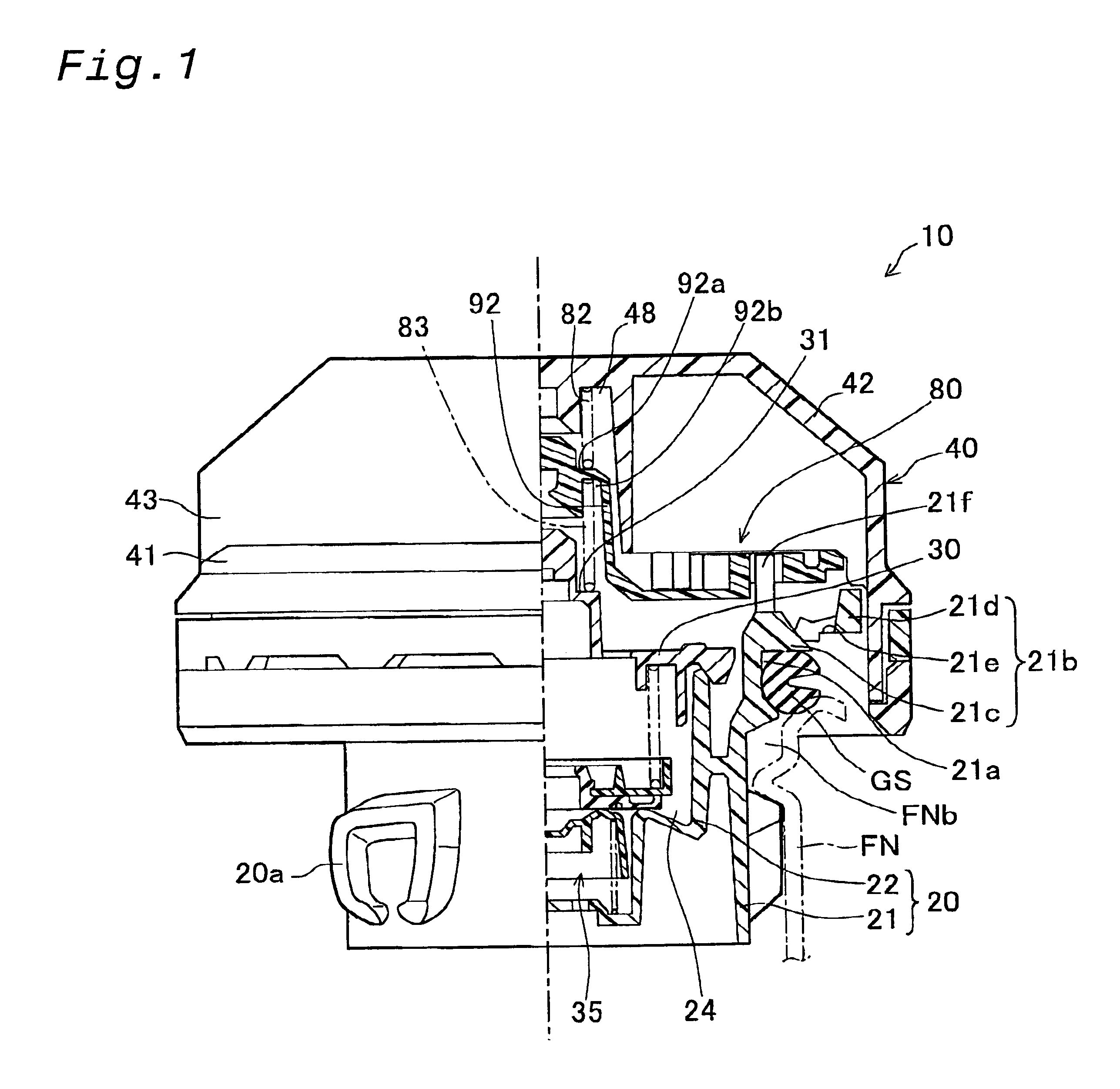
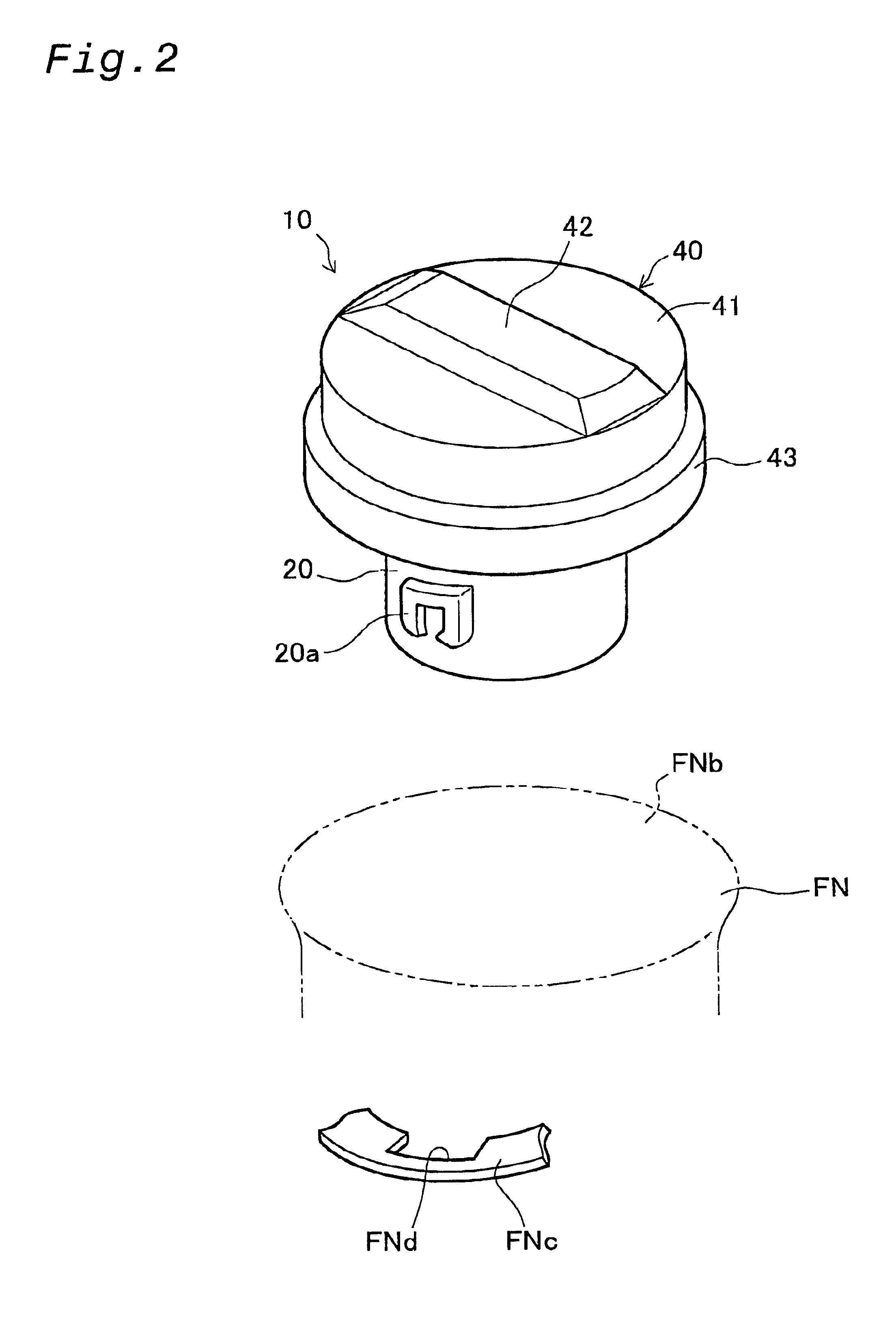
FIG. 1 is a partial cross-sectional view showing a fuel cap 10 (tank cap) according to one embodiment of the present invention. In FIG. 1, the fuel cap 10 is mounted on a filler neck FN having a fueling inlet FNb (tank opening) for supplying fuel to a fuel tank not shown in the figure. The fuel cap 10 comprises a casing main body 20 made of a resin material such as polyacetal resin; a cover 40 having a handle and formed of a resin material such as nylon and mounted on an upper part of the casing main body 20; an inner cover 30 defining a valve chamber 24 by closing an upper opening of the casing main body 20; a pressure regulating valve 35 accommodated in the valve chamber 24; a torque mechanism 80; and a gasket as mounted on an upper portion of the casing main body 20 for sealing against the filler neck FN.

The elements of the tank cap 10 in the embodiment are described in detail below. The casing main body 20 comprises a substantially cylindrical outer tubular body 21 with a casing...


PUM

PropertyMeasurementUnit
angleaaaaaaaaaa
rotational angleaaaaaaaaaa
circumferenceaaaaaaaaaa

Abstract

A fuel cap is equipped with the torque mechanism 80. The torque mechanism 80 comprises the handle engagement element 46a formed on the cover 40; the torque plate 90, having the torque piece engagement element 94b; and a spring. When the cover 40 is rotated in the closing direction, the handle engagement element 46a disengages from torque piece engagement element 94b and the engagement gives the user a feeling of attachment by an audible click. At that time, elastic torque piece 94 elastically deforms so that the handle engagement vertical surface 46b is pushed in the radial direction by the engaging vertical surface 94d, a slot 94c. Conversely, when the cap is rotated in the opening direction, the engaging inclined surface 46c pushes the engaging inclined surface 94e and elastic torque piece 94 inclines with the support end 94a, and thus the cap transitions to a non-engaged state, and the cover 40 is returned to an initial position relative to the casing main body 20. The fuel cap closes the fuel tank fueling inlet with a small value of rotating torque, the disengaging force used for tightening or untightening the cap is small, and operating noise is reduced.

Description

This application claims the benefit of and priority from Japanese Application No. 2001-98088 filed Mar. 30, 2001, the content of which is incorporated herein by reference.BACKGROUND OF THE INVENTION1. Field of the InventionThe present invention relates to a tank cap, having a torque mechanism for closing the opening of a tank with a predetermined rotational torque.2. Description of the Related ArtOne example of known tank caps is described in JP No. 2000-344266A. As shown in FIG. 15, a fuel cap 100 comprises a casing main body 110, a handle 120, and a torque mechanism 130. The torque mechanism 130 comprises handle engagement elements 122 formed on the handle 120, a torque plate 140 having torque piece engagement elements 142, and a spring 132. When the handle 120 is rotated in the closing direction, the handle engagement elements 122 engage with the torque piece engagement elements 142 and disengage with the torque piece engagement elements 142, giving the user a feeling of attachme...

Claims


Application Information

Patent Timeline
Patent Type & Authority Patents(United States)
IPC IPC(8): B60K15/04B60K15/05B65D51/00
CPCB60K15/0406Y10S220/33
Inventor HAGANO, HIROYUKINAKAGAWA, MASAYUKI
Owner TOYODA GOSEI CO LTD
Why Eureka
Try Eureka