Printer and printer head

a printer head and printing head technology, applied in printing, inking apparatus, other printing apparatus, etc., can solve problems such as deterioration of print quality, inability to prevent irregular characteristics, and defects for full practical us

Inactive Publication Date: 2004-09-21
SONY CORP
View PDF16 Cites 52 Cited by
  • Summary
  • Abstract
  • Description
  • Claims
  • Application Information

AI Technical Summary

Problems solved by technology

However, a printer head consisting of such head chips in a conventional fabrication has various problems described below, thereby having defects for full practical use.
This problem is that, for these head chips, irregularity of the characteristics cannot be prevented.
Thus, for example, when printing a background in a single color, a phenomenon occurs that on the boundary part, there appear vertical stripes in the direction of printout, deteriorating quality of the print result.
In this connection, deterioration of print result when using an ink-jet printer is caused not only by the above-mentioned irregularities of head chips, but also by positioning errors of head chips.
However, when using the same color ink-droplets, if deviation of an impact point from a target point is more than a half of a dot diameter, deterioration of print quality is detected.
This means that nozzles need to be positioned with high precision, otherwise a positioning error affects an impact point of an ink droplet.
Therefore, in a printer, even if irregularity of the characteristics of head chips is prevented for practical use, when aligning a plurality of head chips to form a printer head in a conventional fabrication, head chips need to be aligned with very high precision, which is practically difficult, thereby making it inevitable to deteriorate print result.
Moreover, as viewed from the paper feed direction, the nozzle pitches of the head chip 30D are shorter due to the inclination of the head chip, more particularly, the nozzle pitch suddenly changes at the boundary of the adjacent head chip 30C, thereby resulting in deterioration of uniformity of the print result.
In this connection, deterioration of the print result is significant when printing a line image in the paper feed direction.
Additionally, quality deterioration of print result due to positioning error of head chips occurs when printing in different colors, which is detected as deterioration of registration and reproducibility in color.
When preventing quality deterioration of the print result by partly mixing dots produced from the two head chips, if the two head chips are not positioned correctly, a dot print spot by one of the head chip may be misplaced against a dot print spot by the other head chip, thereby deteriorating quality of the print result.
In these cases, as mentioned above, a head-chip array of a conventional fabrication cannot prevent dot misplacement for each color, deteriorating the print quality.
In this connection, if one long head chip having a print width is used instead of a head chip array, it is not possible to fully prevent such misplacement among the arrays.
Furthermore, when creating the longer head having a print width, it is necessary to incorporate the larger number of elements such as heaters and so on into one head chip, thereby lowering the total yield rate.

Method used


Image

  • Printer and printer head
  • Printer and printer head
  • Printer and printer head

Examples


second embodiment

(2) A Second Embodiment

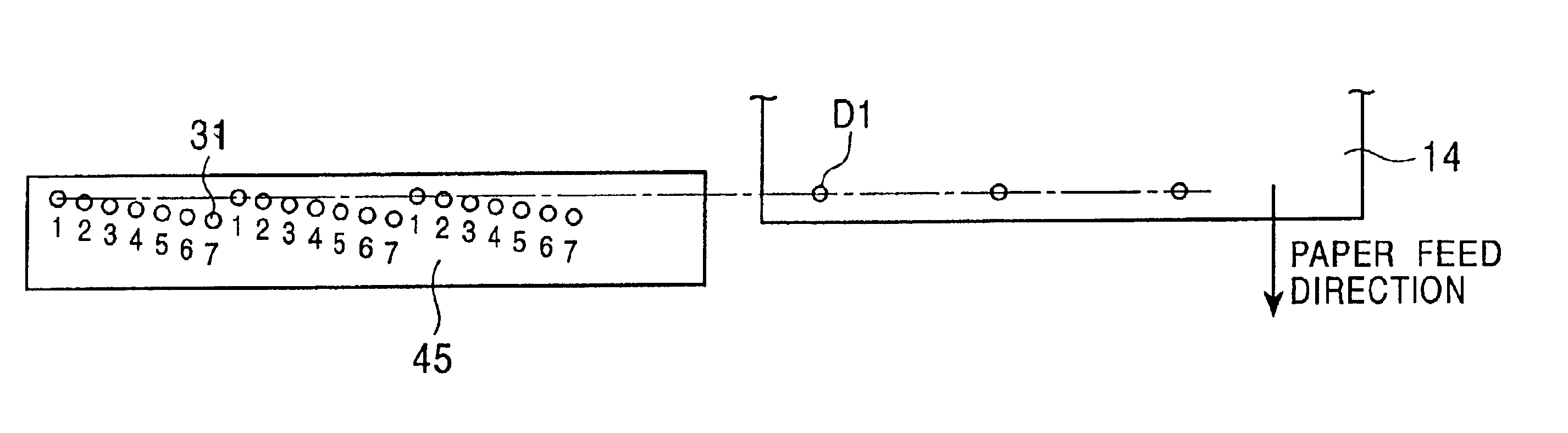
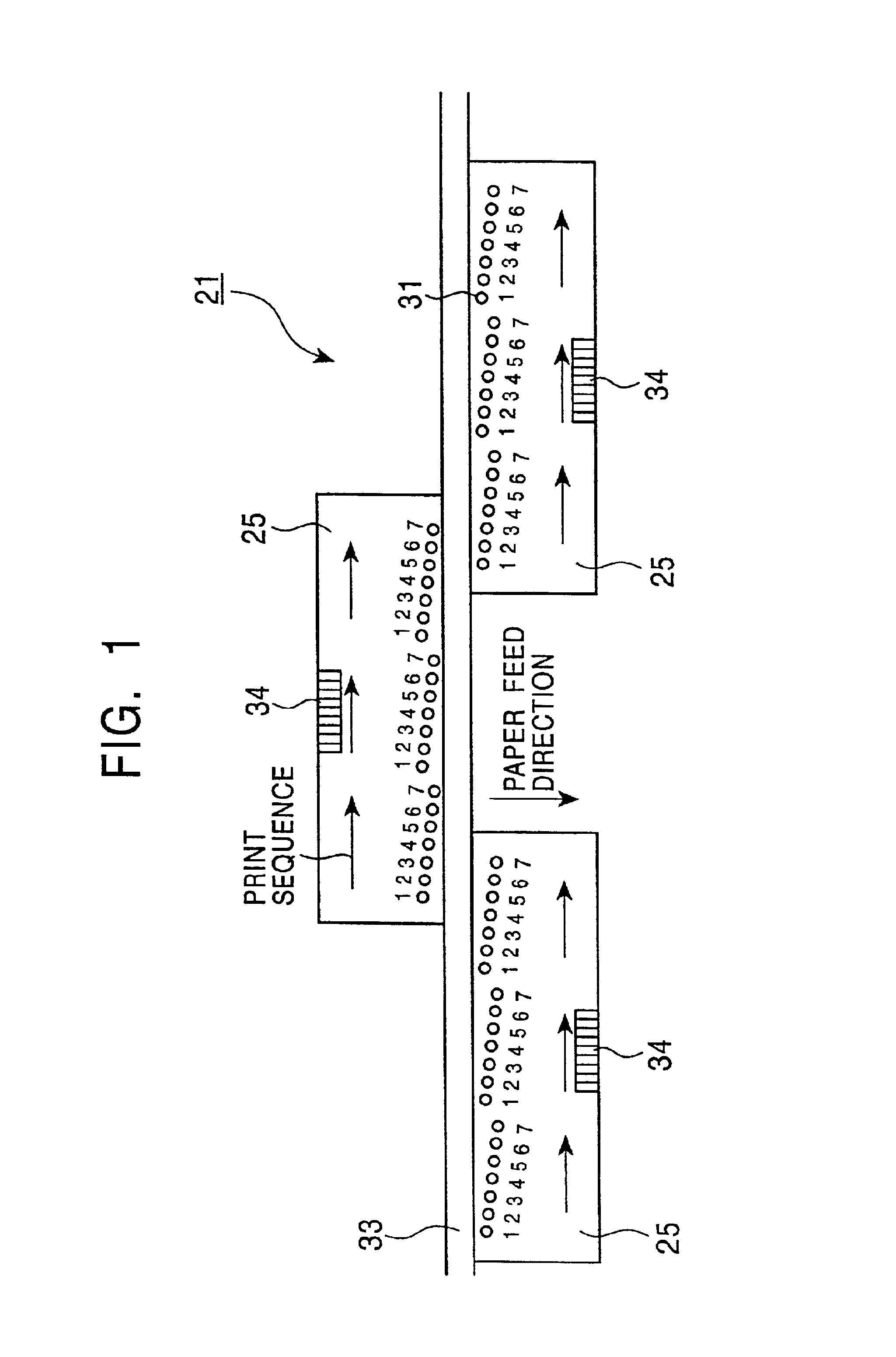
FIG. 21 schematically illustrates, in comparison with FIG. 13, driving of adjacent head chips by the head drive unit 50 of a printer in accordance with the second embodiment of the present invention. In a line printer in accordance with the second embodiment, except that the processing of the head drive unit 50 is different, the configuration is the same as the line printer 11 in accordance with the first embodiment.

The head drive unit 50 sets the driving of each head chips such that, in the overlapped area, when it is nearer to each one of head chips from the center of the overlapped area (shown by one-dot chain line), the number of dots covered by the chip will become bigger. Thus, in FIG. 21, the setting is made such that on the left side of the overlapped area, the left-side chip covers three dots out of four, whereas on the right-side, one dot is covered.

As a result, in this embodiment, in the overlapped area, the gradation is applied such that it is smoo...

third embodiment

(3) A Third Embodiment

FIG. 22 schematically illustrates, in comparison with FIG. 13, driving of adjacent head chips by the head drive unit 50 of a printer in accordance with the third embodiment of the present invention. In a line printer in accordance with the third embodiment, except that the processing of the head drive unit 50 is different, the configuration is the same as the line printer 11 in accordance with the first embodiment.

The head drive unit 50 sets the driving of each head chips such that, in the overlapped area, the head chips are switched to perform printing dots per each line. Thus, instead of the above-mentioned vertical dot array in accordance with the first embodiment, using lateral dot array, in the overlapped area, spots of printing dots are mixed respectively by the two head chips.

In the configuration of FIG. 22, the head chips can be switched to cover printing dots per each line, and in the overlapped area, spots of printing dots can be mixed respectively by...

fourth embodiment

(4) The Fourth Embodiment

FIG. 23 schematically illustrates, in comparison with FIG. 13, driving of adjacent head chips by the head drive unit 50 of a printer in accordance with the fourth embodiment of the present invention. In a line printer in accordance with the fourth embodiment, except that the processing of the head drive unit 50 is different, the configuration is the same as the line printer 11 in accordance with the first embodiment.

The head drive unit 50 sets the driving of two head chips such that, spots of printing dots are allocated in accordance with the combination of the first and the third embodiments. This means that printing dots is allocated such that as in the paper feed direction, the head chips are switched to cover printing dots per each line. Moreover, in a direction perpendicular to the paper feed direction, printing dot is allocated such that the head chips are switched alternatively. Thus, the line printer 11 can produce the average print result of the cha...


PUM


Abstract

A printer head with overlapping nozzles. A plurality of head chips are formed in an array pattern on the printer head wherein a plurality of nozzles are associated with each head chip. Nozzles associated with one head chip and nozzles associated with an adjacent head chip partly overlap to form an overlapped area. When an ink-ejecting mechanism drives across a print object, the nozzles of the one head chip and the nozzles of the adjacent head chip respectively eject inks which are mixed in the overlapped area to reduce dot density differences on the print object.

Description

1. Field of the InventionThe present invention relates to a printer and printer head, and more particularly, to a line printer using an ink-jet method.2. Description of the Related ArtConventionally, ink-jet printers have been designed to print a desired image, characters and so on by ejecting ink droplets onto the paper selectively by the nozzles placed sequentially in a direction substantially perpendicular to the paper-feed direction.In such a line printer, a thermal-method printer for example, as disclosed in Japanese Unexamined Patent Application Publication No. 2001-71495, head chips are used to form a printer head in order to improve yield and to avoid influence of wiring resistance. In this case, the head chip is formed such that ink is held in ink bed, and is heated by a heater to eject ink droplets from the nozzles. The head chip is made of one semiconductor substrate on which heaters and so on are created for a plurality of such nozzles. In a printer, a plurality of such ...

Claims


Application Information

Patent Timeline
Patent Type & Authority Patents(United States)
IPC IPC(8): B41J2/145B41J2/155B41J2/21B41J2/01
CPCB41J2/1433B41J2/155B41J2/2103B41J2002/14475B41J2202/20
Inventor IKEMOTO, YUICHIROTAKENAKA, KAZUYASUANDO, MAKOTOHORII, SHINICHI
Owner SONY CORP
Why Eureka
Try Eureka