Multimode system for injecting an air/fuel mixture into a combustion chamber

a multi-mode system and combustion chamber technology, applied in mechanical equipment, machines/engines, lighting and heating apparatus, etc., can solve the problems of non-uniform air/fuel mixture, inability to meet the above-specified operating requirements correctly, limited formation of pollutants such as nitrogen oxides, etc., to reduce the risk of coking, limit polluting emissions, and mitigate drawbacks

Inactive Publication Date: 2004-10-05
SN DETUDE & DE CONSTR DE MOTEURS DAVIATION S N E C M A
View PDF6 Cites 32 Cited by
  • Summary
  • Abstract
  • Description
  • Claims
  • Application Information

AI Technical Summary

Benefits of technology

The present invention thus seeks to mitigate such drawbacks by proposing an injection system comprising a multimode system for injecting an air / fuel mixture which enables an air / fuel mixture to be prepared that is optimized both for low speed conditions and for high speed conditions in order to limit polluting emissions. The invention also seeks to provide an injection system that limits the risks of coking and prevents any ingress of fuel into the air feed system.
As a result, the injection system makes it possible both to generate an air / fuel mixture that is uniform and lean under high speed conditions in order to limit polluting emissions of nitrogen oxide, and also to create pockets of gas in stoichiometric proportion under low speed conditions in order to guarantee lighting and combustion flame stability in the chamber while still keeping emissions of carbon monoxide down. The air / fuel mixture is injected in multiple modes depending on the operating conditions of engine. The distribution of fuel in the injection system can thus be under complete control as a function of the mass of air introduced by the air injection means. In addition, injecting fuel in directions that are perpendicular to the flows of air coming from the air injection means improves homogenization of the air / fuel mixture.
Advantageously, the fuel injection orifices of the first and second fuel admission circuits are regularly distributed around the longitudinal axis and occupy angular positions that are mutually offset so as to improve homogenization of the mixture.
A single feed duct can feed fuel to the first and second fuel admission circuits, e.g. via a plurality of concentric tubes. Thus, fuel feed takes place via a single duct, thereby limiting the risks of coking and taking advantage of the cooling that is obtained by fuel flowing in the circuits.

Problems solved by technology

These requirements imply modes of operation that are often mutually incompatible.
Conversely, the formation of pollutants such as nitrogen oxides is limited by making combustion take place in a mixture that is lean and uniform.
A single-mode fuel injection system as described above cannot satisfy all of the above-specified operating requirements correctly.
Fuel injection in such systems takes place in zones where the mass of air injected is lower, thereby tending to make the air / fuel mixture non-uniform.
In particular, when operating at idling speed, such injection systems do not operate properly, which leads to high levels of carbon monoxide emissions.
Although that solution would appear to be satisfactory, a combustion chamber having two heads remains difficult to control and expensive, given the duplication of the number of fuel injectors compared with a conventional single-head combustion chamber.
However, the injection system described in that patent also presents drawbacks.
The injection orifices are fed with fuel, in particular via a plurality of feed ducts, thereby considerably increasing the risk of fuel coking.
In addition, the particular disposition of the fuel injection orifices relative to the air injection leads to significant risks of fuel penetrating into the air injection circuit.

Method used


Image

  • Multimode system for injecting an air/fuel mixture into a combustion chamber
  • Multimode system for injecting an air/fuel mixture into a combustion chamber
  • Multimode system for injecting an air/fuel mixture into a combustion chamber

Examples


Embodiment Construction

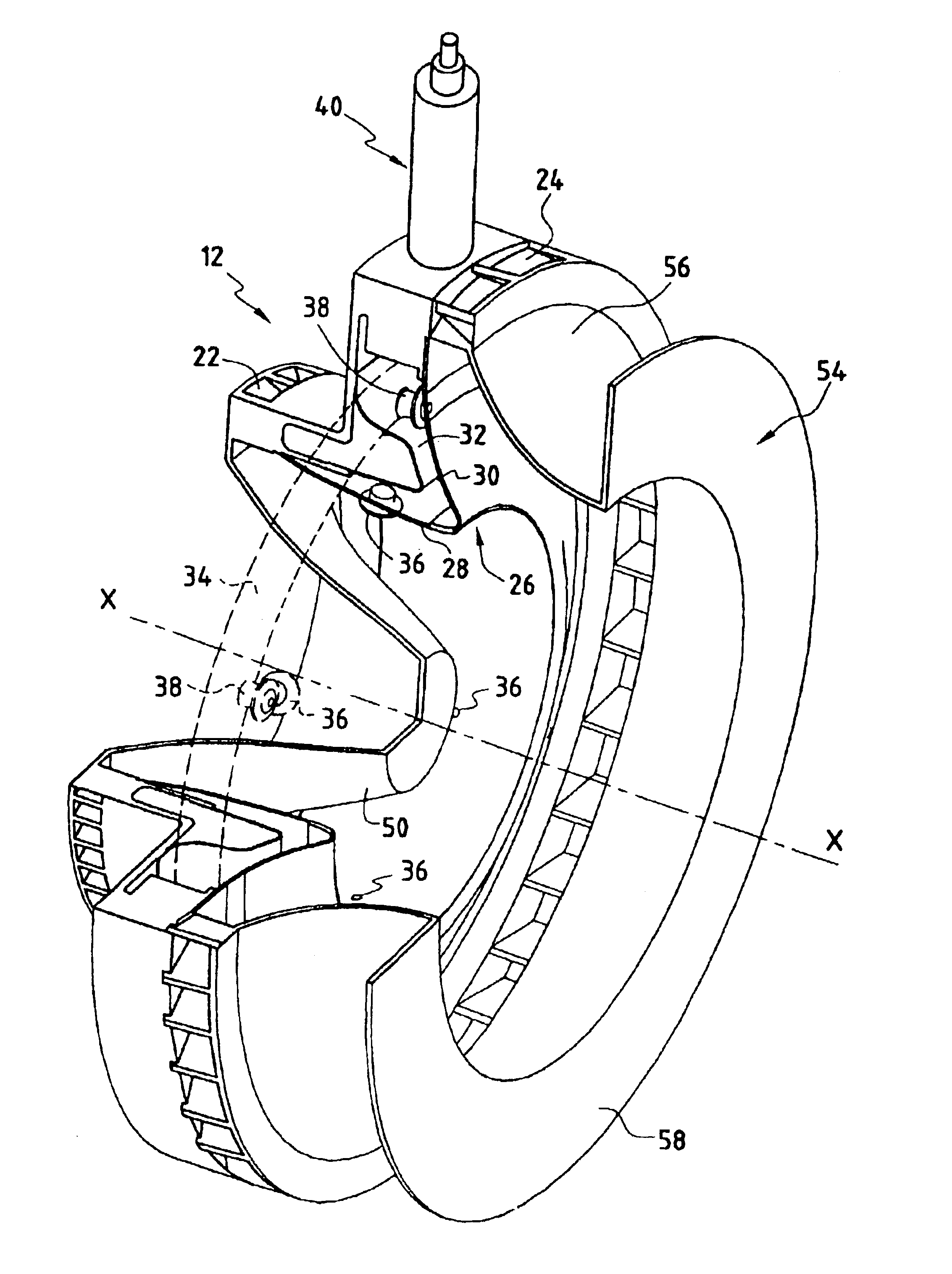
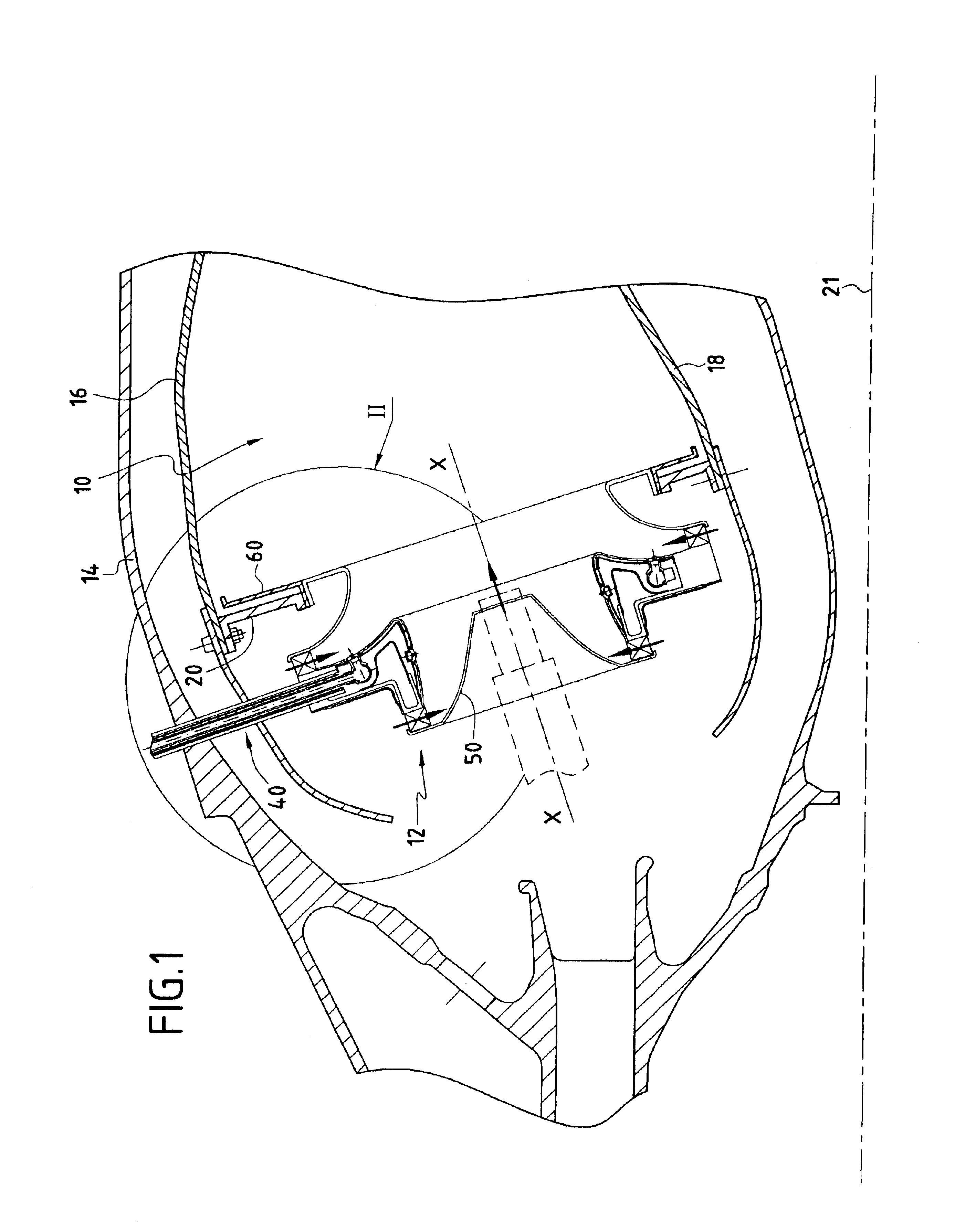
Reference is made to FIG. 1 which shows a portion of a combustion chamber 10 in section, the chamber being fitted with a plurality of systems 12 for injecting an air / fuel mixture. The combustion chamber 10 is secured to an outer casing 14 by fixing means that are not shown. By way of example, it is of the annular type and it is defined by two annular walls 16 and 18 connected together at an upstream end by an annular end wall 20 for the chamber. The chamber end wall 20 has a plurality of openings that are regularly spaced apart in circular manner about an axis 21 of the gas turbine engine that is fitted with such a combustion chamber. An injection system 12 of the invention is mounted in each of these openings. The injection systems prepare a mixture of air and fuel that is to be burnt in the combustion chamber 10. The gas coming from said combustion flows downstream from the chamber prior to being fed to a high pressure turbine.

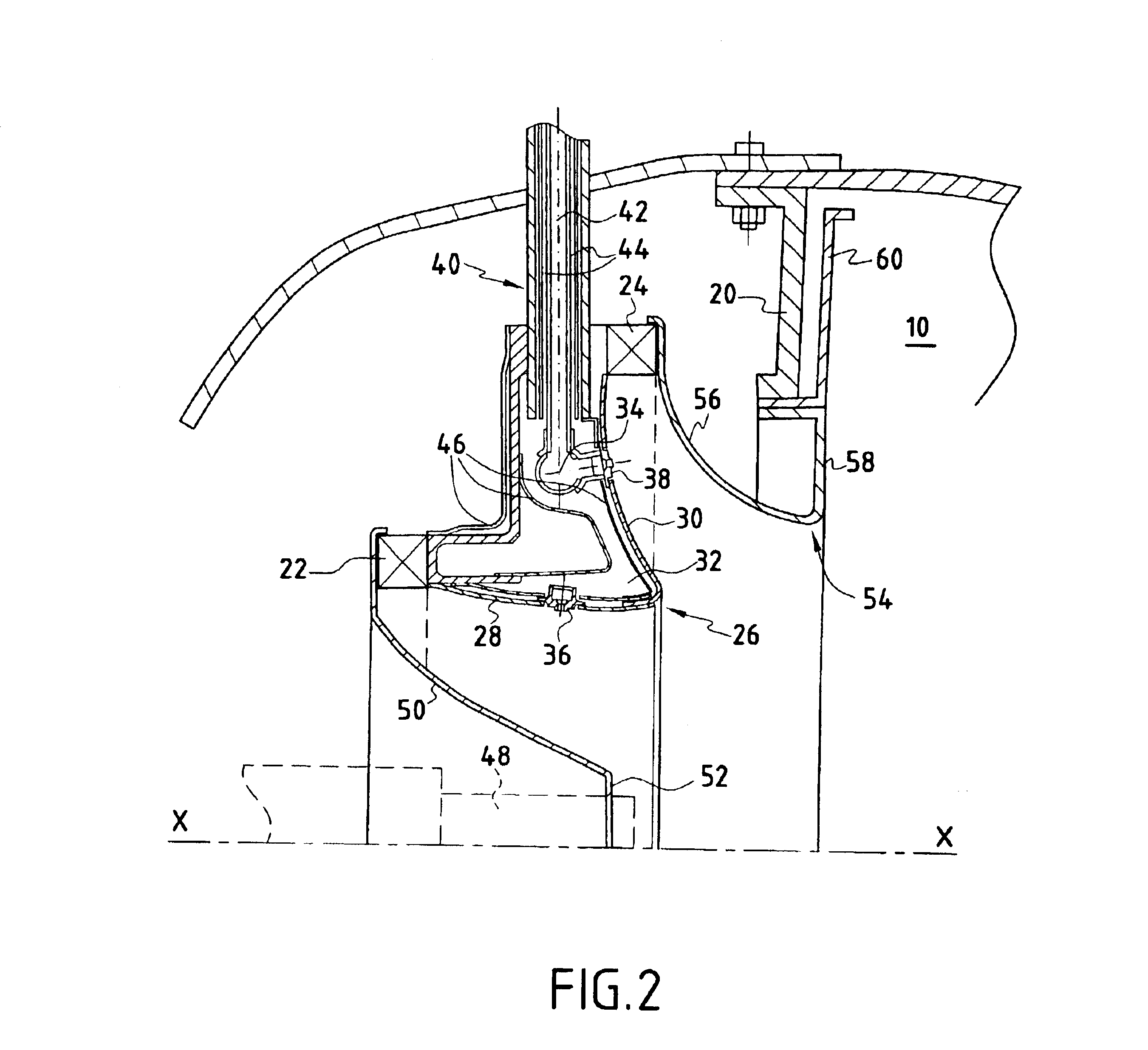
As shown more particularly in FIG. 2, the injection sy...


PUM


Abstract

The invention provides an injection system for injecting an air / fuel mixture into a combustion chamber of a gas turbine engine, the injection system having a longitudinal axis and comprising fuel injection means, interposed between first and second air injection means, the fuel injection means being disposed in an annular internal cavity of a Venturi, the fuel injection means comprising at least a first fuel admission circuit provided with at least one fuel injection orifice, and a plurality of second fuel admission circuits independent from the first fuel admission circuit(s), each being provided with at least one fuel injection orifice so as to define a plurality of independent modes of injecting the air / fuel mixture depending on determined operating speeds of the engine, the fuel injection orifice of the first fuel admission circuit being formed in the upstream wall of the Venturi so as to inject fuel towards the combustion chamber in a general direction that is substantially perpendicular to a flow of air coming from the first air injection means, and the fuel injection orifices of the second fuel admission circuits being formed in the downstream wall of the Venturi so as to inject fuel towards the combustion chamber in a general direction that is substantially perpendicular to a flow of air coming from the second air injection means.

Description

The present invention relates to the general field of systems for injecting fuel into a combustion chamber of a gas turbine engine. More particularly, the invention relates to a system for injecting an air / fuel mixture, which system provides multimode fuel injection enabling at least two independent modes to be defined for injecting the air / fuel mixture, depending on predetermined operating speeds of the engine.In each injection system of a conventional combustion chamber of a gas turbine engine, fuel is injected in single mode manner via a fuel injector. Two air swirlers centered on the fuel injector deliver respective radial flows of air downstream from the point of fuel injection so as to mix the air and fuel that are to be injected into the combustion chamber and then burnt. The flows of air coming from the two swirlers are generally defined by a Venturi interposed between said swirlers, and a bowl mounted downstream therefrom accelerates the flow of the air / fuel mixture towards...

Claims


Application Information

Patent Timeline
Patent Type & Authority Patents(United States)
IPC IPC(8): F23R3/28F23R3/14F23R3/04F23R3/34F23R3/30
CPCF23R3/14F23R3/343F23R3/28
Inventor CALVEZ, GWENAELLEFEDER, DIDIERMICHAU, MARIONRAVET, FREDERICRODRIGUES, JOSESCHULER, ALAINTIEPEL, ALAINVIGUIER, CHRISTOPHE
Owner SN DETUDE & DE CONSTR DE MOTEURS DAVIATION S N E C M A
Why Eureka
Try Eureka