Stub having an optical fiber

a technology of optical fiber and stub, which is applied in the field of fiber optics, can solve the problems of difficult handling and placement of optical fiber in an assembly

Inactive Publication Date: 2004-10-19
STRATOS INT
View PDF15 Cites 27 Cited by
  • Summary
  • Abstract
  • Description
  • Claims
  • Application Information

AI Technical Summary

Benefits of technology

It is another object of the present invention to provide a terminated optical fiber which includes a stub attached to the optical fiber which provides for shorter set-up times and thus increased productivity.
It is yet another object of the present invention to provide a cleaved and lensed optical fiber which is robust and rugged enough not to be damaged by a vibrating feeding machine which is part of an assembly line process to feed the device to another structure for assembly.
Thus, the device of the invention is superior to existing solutions since the stub having the optical fiber is connectorized. The device can be assembled in large quantities and stored. The device can be assembled into a housing containing an optoelectronic device or it can be assembled onto a board which has unfinished or un-connectorized optical fiber which need to be terminated. Thus, the device of the invention is more cost effective than prior art devices.

Problems solved by technology

Both the cleaving step and the lensing step of the prior art require numerous time consuming set-up operations, low yields, and result in difficulty in handling and placing the optical fiber in an assembly.

Method used


Image

  • Stub having an optical fiber
  • Stub having an optical fiber
  • Stub having an optical fiber

Examples


Embodiment Construction

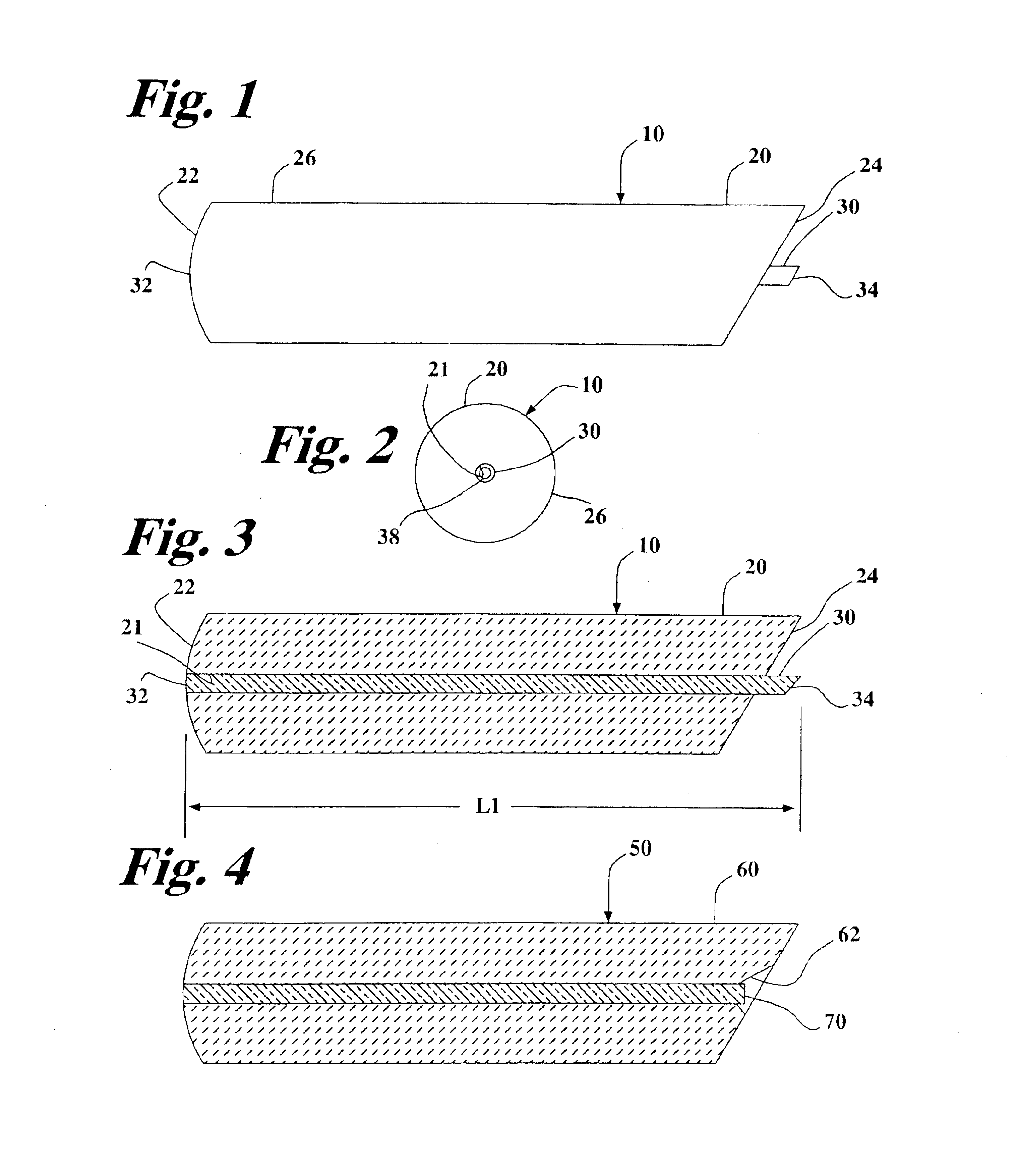
Referring now to the drawings, wherein like reference numerals designate identical or corresponding parts throughout the several views, and more particularly to FIGS. 1-3 thereof, is a device 10 including a stub 20 and an optical fiber 30.

FIG. 1 is a plan view of the device 10 which includes the stub 20, and the optical fiber 30. The stub 20 includes a first end 22, and a second end 24. The optical fiber 30 includes a first end 32, and a second end 34.

FIG. 2 is a plan view of an end of the device 10 showing the profile of the cylindrically shaped surface 26 of the stub 20. Also shown is the aperture 21 of the stub 20.

FIG. 3 is a cross-sectional view of the device 10 of FIG. 1. The first end 32 of the optical fiber 30 is polished so as to be flush with the first end 22 of the stub 20. The first end 22 of the stub 20 and the first end 32 of the optical fiber 30 are polished so as to be in conformity with the physical contact (PC) surface finish standard so as to allow the device 10 to...


PUM

PropertyMeasurementUnit
lengthaaaaaaaaaa
angleaaaaaaaaaa
physicalaaaaaaaaaa

Abstract

A device includes a stub, and an optical fiber. The stub has an aperture, and a first end and a second end. The optical fiber is mounted in the aperture of the stub. The optical fiber has a first end and a second end. The first end of the optical fiber is polished so as to be flush with the first end of the stub. The second end of the optical fiber is cleaved at a predetermined position so as to provide for a predetermined length of the optical fiber measured from the first end of the optical fiber to the second end of the optical fiber.

Description

1. Field of the InventionThe present invention pertains to the field of fiber optics. The invention more particularly concerns an optical fiber mounted in a stub where one end of the optical fiber is cleaved and the other end of the optical fiber is polished. Glass material is used to construct the optical fiber or waveguide.2. Discussion of the BackgroundCleaving an optical fiber by mechanical means is known in the art and cleaving with a laser or cutting beam is also known in the art and is disclosed in U.S. Pat. Nos. 4,710,605, and 6,139,196. U.S. Pat. Nos. 4,710,605, and 6,139,196 are hereby incorporated herein by reference. U.S. Pat. No. 4,710,605 discloses a single optical fiber mounted in a fixture where the laser cleaves a bare optical fiber. U.S. Pat. No. 6,139,196 discloses a single optical fiber, including a fiber jacket surrounding the optical fiber, mounted in a fixture where the laser cleaves the fiber jacket and the optical fiber. In both cases, the cleaved optical fi...

Claims


Application Information

Patent Timeline
Patent Type & Authority Patents(United States)
IPC IPC(8): G02B6/25G02B6/42
CPCG02B6/25G02B6/421Y10T29/49176Y10T29/49183Y10T29/49174G02B6/44G02B6/42G02B6/02
Inventor DURRANT, RICHARD C. E.LANTSMAN, ALEKSANDRMEAD, DAVID G.WARNES, CHRISTOPHER M.WASHBURN, THEODORE
Owner STRATOS INT
Why Eureka
Try Eureka