Navigational device for an underwater diver

a navigation device and underwater technology, applied in underwater equipment, underwater equipment, using reradiation, etc., can solve the problems of limiting the ability of divers to navigate with any degree, difficult for divers to accurately navigate between various locations or points of interest while submerged, and poor visibility

Inactive Publication Date: 2004-10-19
MCGEEVER JR JOHN F
View PDF26 Cites 64 Cited by
  • Summary
  • Abstract
  • Description
  • Claims
  • Application Information

AI Technical Summary

Problems solved by technology

In the field of underwater diving, it is sometimes difficult for a diver to accurately navigate between various locations or points of interest while submerged.
One factor limiting a diver's ability to navigate with any degree of precession is poor visibility.
Poor visibility can greatly reduce the ability of the diver to successfully descend from a dive boat or shore location and return confidently to the same location on their ascent.
Furthermore, it can be very difficult for a diver to navigate between geographically separated underwater locations of interest when the diver's visibility of the locations is obscured.
Small errors in directional travel can result in the diver being a large distance from the intended target location.
While a diver can in some instances ascend to the surface to regain their directional baring, this in most cases can be extremely dangerous due to surface obstructions such as watercraft.
Another limiting factor to the success of a diver's navigation is time, which directly correlates to the diver's finite air supply.
As stated above, while the compass provides the diver with the ability to determine their heading, when used over large distances small navigational errors can result in large deviations from the desired course of travel and the desired destination.
While this method will indicate the diver's approximate position relative to the transmitter, it will not provide a diver their location in relation to multiple reference points.
Additionally, the cost and complexity of the various transmitters and receivers is prohibitive to most recreational divers.
It is also a legal and safety requirement in various jurisdictions for a diver to dive with a dive float and flag deployed at all times. The Silvey patent does not allow for this type of deployment.
While this method will indicate the diver's approximate position relative to the transmitter, it will not provide a diver their location in relation to multiple reference points without the addition of a transmitter for each additional reference point.
Additionally, the cost and complexity of the various transmitters and receivers is prohibitive to most recreational divers.

Method used


Image

  • Navigational device for an underwater diver
  • Navigational device for an underwater diver
  • Navigational device for an underwater diver

Examples


Embodiment Construction

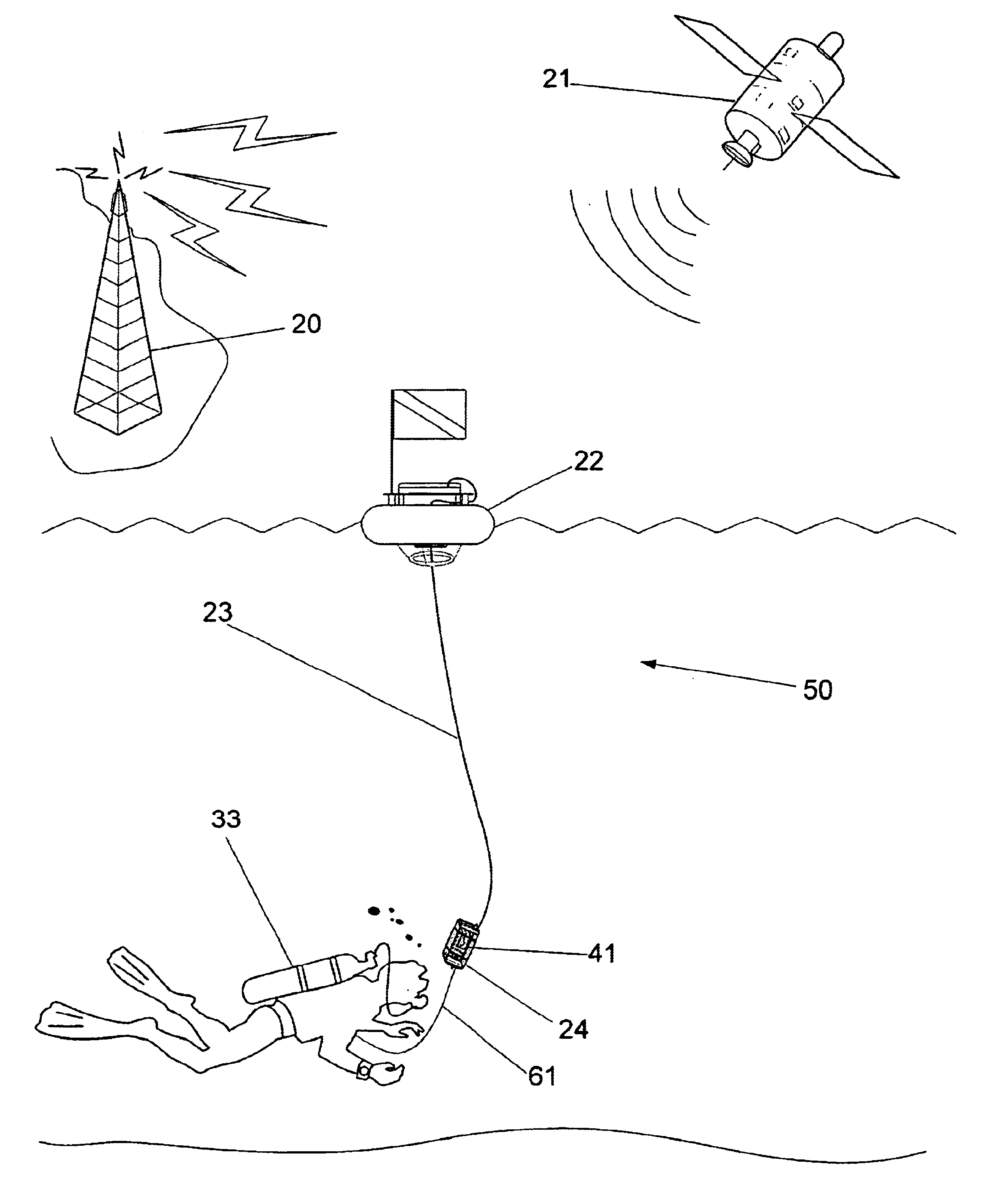
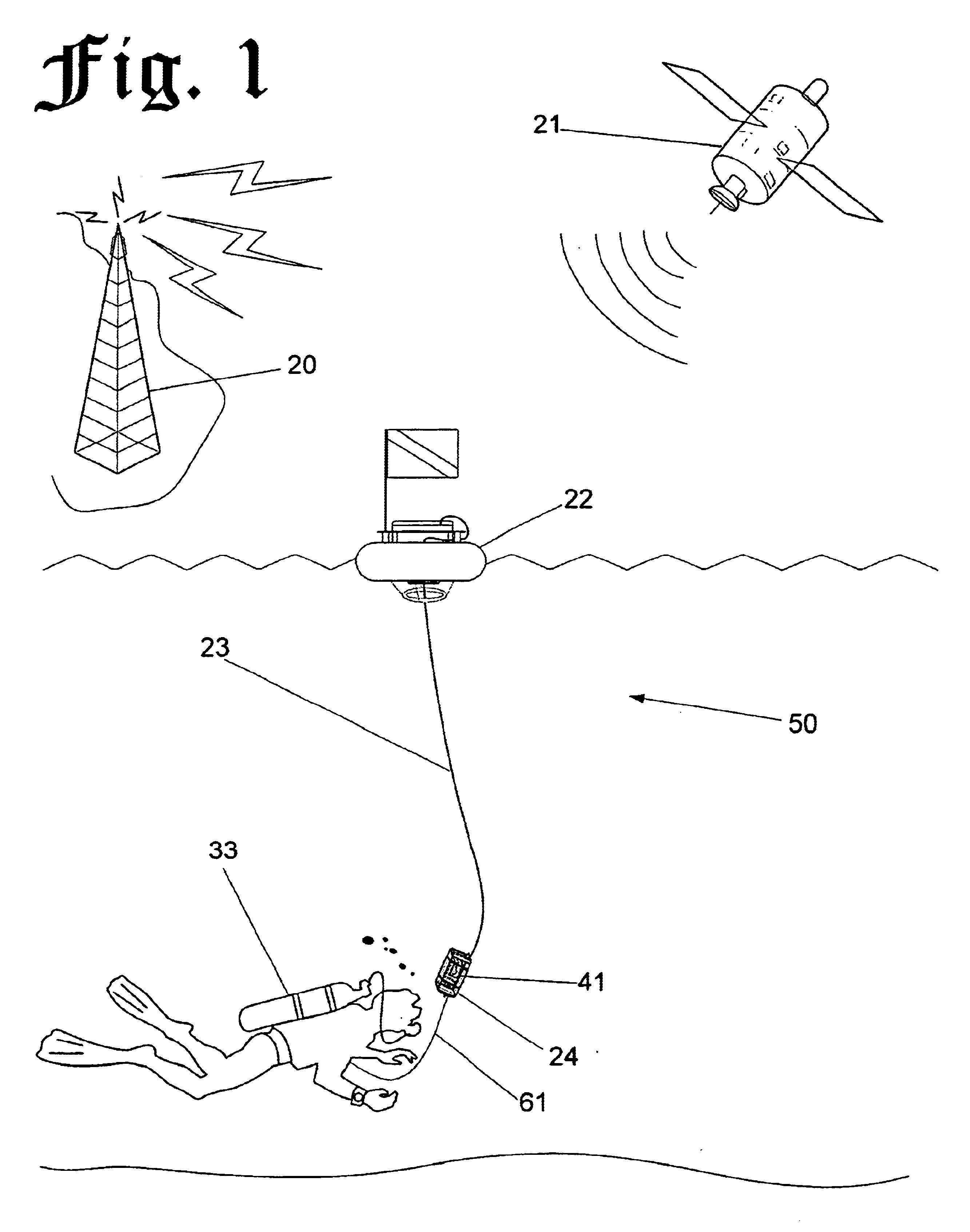
FIG. 1 is a perspective view of an Underwater Diver Navigation Device (50) according to one embodiment of the present invention. The Underwater Diver Navigation Device (50), or navigation device, comprises a SCUBA Flag / Antenna Float (22), or float, a Signal / Umbilical Cable (23), a GPS Capsule (24), and a GPS Receiver / Display (41).

Also depicted in FIG. 1 are a Global Positioning System Satellite (21), or GPS Satellite, and a Terrestrial Differential Global Positioning System (DGPS) Antenna (20), or DGPS Antenna, and a SCUBA Diver (33), who is represented as the potential end-user of the present invention.

The float is connected to the GPS Capsule (24) via the Signal / Umbilical Cable (23), or umbilical. The SCUBA Diver (33), or diver, is attached to the GPS Capsule (24) via a Safety Cord (61).

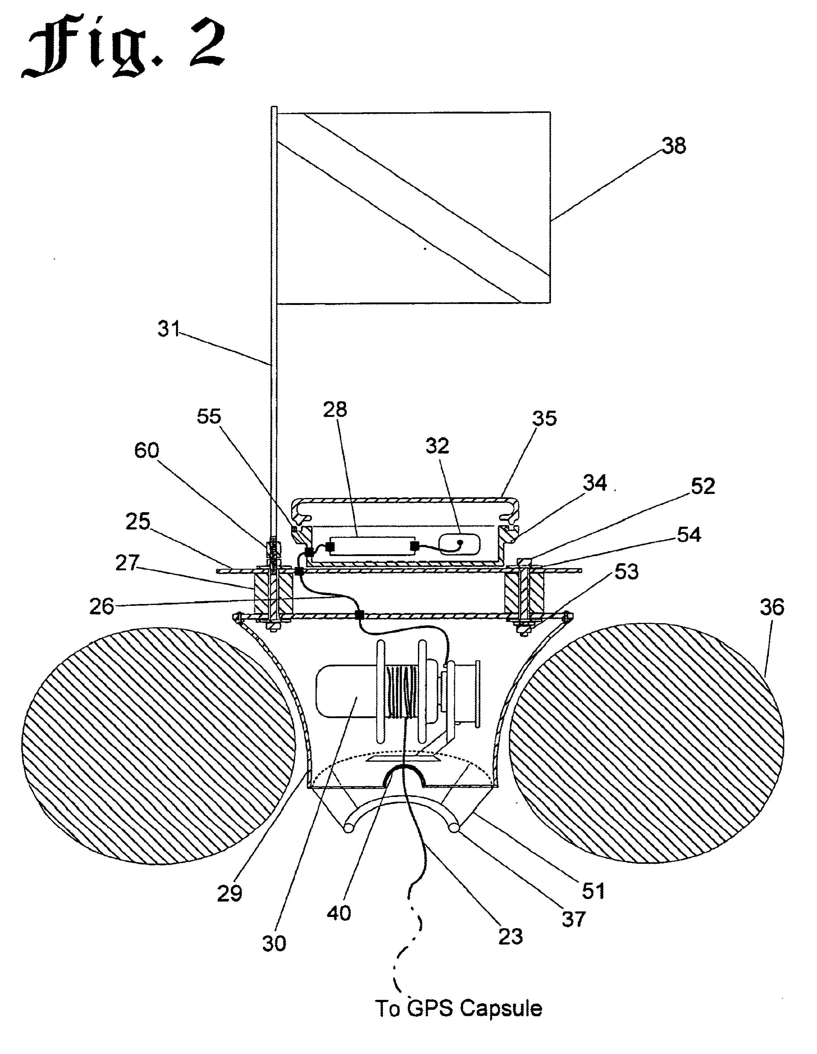
FIG. 2 is a cross-sectional view of the SCUBA Flag / Antenna Float (22) component of the Underwater Diver Navigation Device (50) of FIG. 1. The cross-section of FIG. 2 is taken along line `2` of FIG....


PUM


Abstract

An apparatus for providing Global Positioning System (GPS) position data to an underwater diver for use in navigation is comprised of a SCUBA Flag / Antenna Float, positioned on the surface of the water, containing a Spring-loaded Cable Reel which is connected via a Signal Umbilical Cable to a GPS Capsule carried by the underwater diver. A GPS Antenna and power supply provide a signal to a GPS Receiver / Display which is encased in the GPS Capsule. The diver views icons displayed on the GPS Receiver to determine his / her current position in relation to previously entered waypoints, or geographical coordinates, such as a wreck, dive boat, or locations of interest plotted by the diver during the dive. The position information displayed by the GPS receiver enables the diver to navigate to and from the various locations or geographical coordinates while submerged.

Description

BACKGROUND OF INVENTIONThe present invention relates generally to the field of underwater diving, and in particular to a method and apparatus, utilizing the Global Positioning System (GPS) to provide underwater divers with navigational information.BACKGROUND--DISCUSSION OF PRIOR ARTIn the field of underwater diving, it is sometimes difficult for a diver to accurately navigate between various locations or points of interest while submerged. One factor limiting a diver's ability to navigate with any degree of precession is poor visibility. Poor visibility can greatly reduce the ability of the diver to successfully descend from a dive boat or shore location and return confidently to the same location on their ascent. Furthermore, it can be very difficult for a diver to navigate between geographically separated underwater locations of interest when the diver's visibility of the locations is obscured.The diver's currently recognized method of navigation involves the use of an underwater ...

Claims


Application Information

Patent Timeline
Patent Type & Authority Patents(United States)
IPC IPC(8): B63C11/02B63C11/26G01S1/00G01S5/14G01C21/20G01S19/19G01S19/35
CPCB63C11/26G01C21/20G01S19/14G01S19/36G01S19/42G01S19/19Y10S367/907G01S19/41
Inventor MCGEEVER, JR., JOHN F.
Owner MCGEEVER JR JOHN F
Why Eureka
Try Eureka