Wireless communication system and image forming device

a wireless communication and image forming technology, applied in the field of wireless communication systems, can solve the problems of weak electricity supplied to the wireless communication tags by electromagnetic induction, tag consumes electric power, and it is difficult to dispose of the transceiver antenna (the main body side antenna)

Inactive Publication Date: 2004-10-19
FUJIFILM BUSINESS INNOVATION CORP
View PDF8 Cites 34 Cited by
  • Summary
  • Abstract
  • Description
  • Claims
  • Application Information

AI Technical Summary

Benefits of technology

In the wireless communication system relating to the present invention, the tag side antenna is supported by the cartridge accessory such that the coil axis of the tag side antenna substantially intersects (is substantially orthogonal to) an insertion / removal direction of the cartridge accessory with respect to a cartridge attachment / detachment portion. Hence, there is no need for the tag side antenna to be disposed so as to cover the end surface portion in the insertion / removal direction of the cartridge accessory. Thus, even if structures, components and the like are disposed at the end surface portion of the cartridge accessory, these structures, components and the like will not be impeded, and the wireless communication tag can be easily mounted at the cartridge accessory.
Further, in the wireless communication system relating to the present invention, the main body side antenna is disposed at the device main body such that the coil axis of the main body side antenna substantially intersects (is substantially orthogonal to) the insertion / removal direction, and such that the main body side antenna faces the tag side antenna along a coil axis orthogonal direction, which intersects the coil axis of the main body side antenna. Thus, there is no longer any need to dispose the main body side antenna at a portion opposing the end surface portion of the cartridge accessory in the device main body. Therefore, even if there are structures, components and the like disposed at the portion opposing the end surface portion of the cartridge accessory in the device main body, these structures, components and the like will not be impeded, and the main body side antenna can be easily disposed at the device main body.
Specifically, for example, the main body side antenna may be disposed in a space between a plurality of cartridge accessories in the device main body, or in a space between the device main body and an upper end portion or lower end portion of the cartridge accessories, or the like. Such spaces (dead spaces) have rarely been effectively used heretofore. The main body side antenna can easily be made to oppose the tag side antennas while being sufficiently close to the tag side antennas. Therefore, the main body side antenna can be disposed efficiently in space inside the device main body, and information communication can be reliably performed by electromagnetic waves between the wireless communication device and the wireless communication tags. In particular, if the main body side antenna is disposed between a plurality of cartridge accessories in the device main body, a front surface portion and a back surface portion of a single main body side antenna can be made to oppose different tag side antennas. Thus, even if the main body side antenna is made smaller, electromagnetic transmission and reception can be reliably performed between the single main body side antenna and the two tag side antennas.
Therefore, according to the image forming device relating to the present invention, as is clear from the foregoing explanation of the wireless communication system relating to the present invention, even if structures, components and the like are disposed at the end surface portion of the cartridge accessory, the wireless communication tag can easily be attached to the cartridge accessory so as not to impede these structures, components and the like. Moreover, even if structures, components and the like are disposed at a portion of the device main body that opposes the end surface portion of the cartridge accessory, the main body side antenna can easily be disposed at the device main body so as not to impede these structures, components and the like.
As a result, for example, the main body side antenna may be disposed in a space between a plurality of cartridge accessories in the device main body of the image forming device, in a space between the device main body and an upper end portion or lower end portion of the cartridge accessories, or the like. These spaces (dead spaces) have rarely been effectively used heretofore. Thus, the main body side antenna can easily be made to oppose the tag side antennas while being sufficiently close to the tag side antennas. Therefore, the main body side antenna can be disposed efficiently in the space inside the device main body, and electricity supply by electromagnetic induction and radio communication can be reliably performed between the wireless communication device and the wireless communication tags.

Problems solved by technology

When a wireless communication tag attached to a cartridge accessory as described above is performing wireless communication, information processing or the like, the tag consumes electric power.
Here, the electricity supplied to the wireless communication tags by electromagnetic induction is weak.
Therefore, in an image forming device in which the number of cartridge accessories is large, such as a color laser printer or the like, it is difficult to dispose the transceiver antenna (the main body side antenna) at the device main body such that the transceiver antenna is sufficiently close to and faces the cartridge accessory transceiver antennas (the tag side antennas), without the device becoming large.
Such spaces (dead spaces) have rarely been effectively used heretofore.
These spaces (dead spaces) have rarely been effectively used heretofore.

Method used


Image

  • Wireless communication system and image forming device
  • Wireless communication system and image forming device
  • Wireless communication system and image forming device

Examples


Embodiment Construction

FIGS. 9 and 10 show first and second variant examples of a wireless communication system in a laser printer relating to the present embodiment.

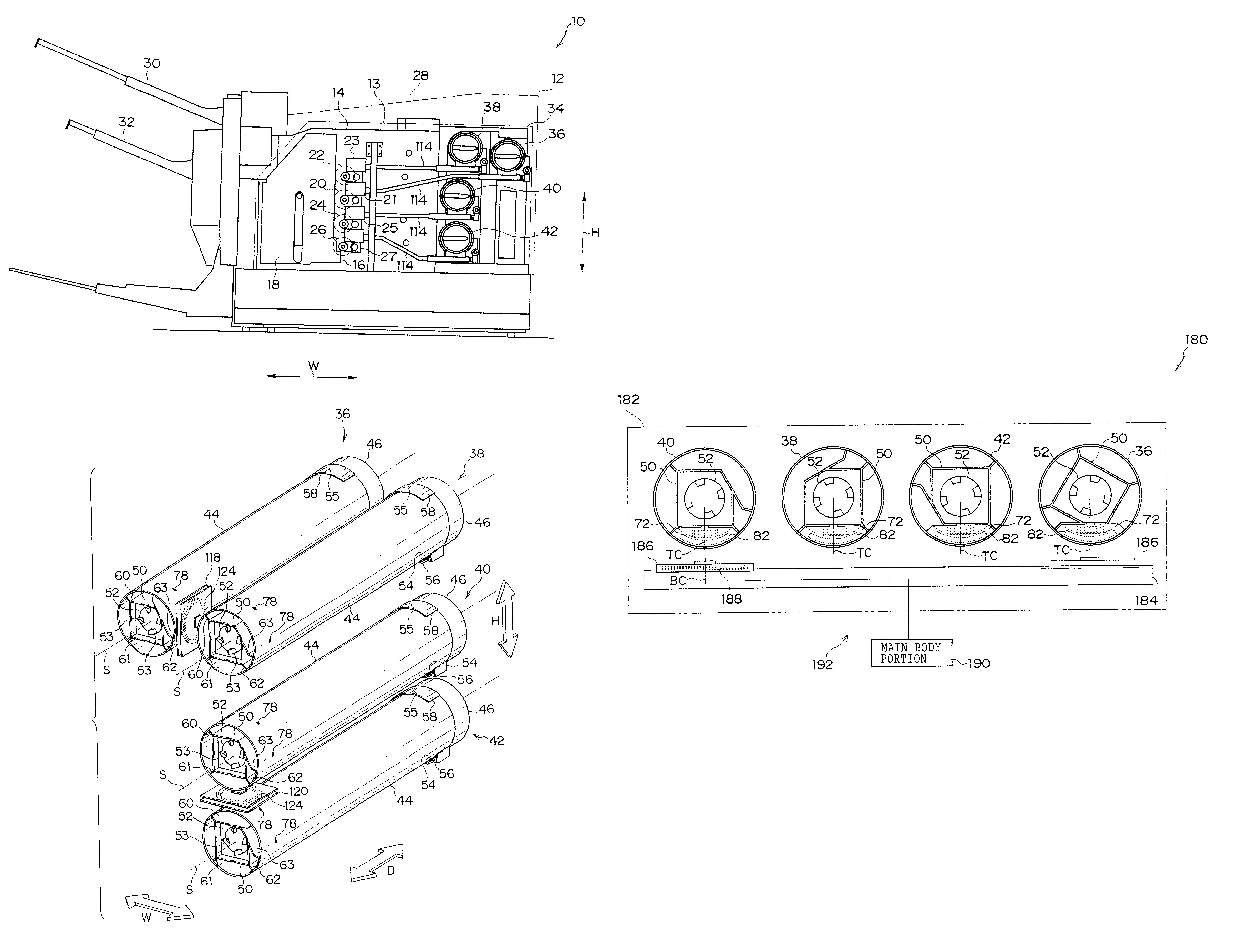
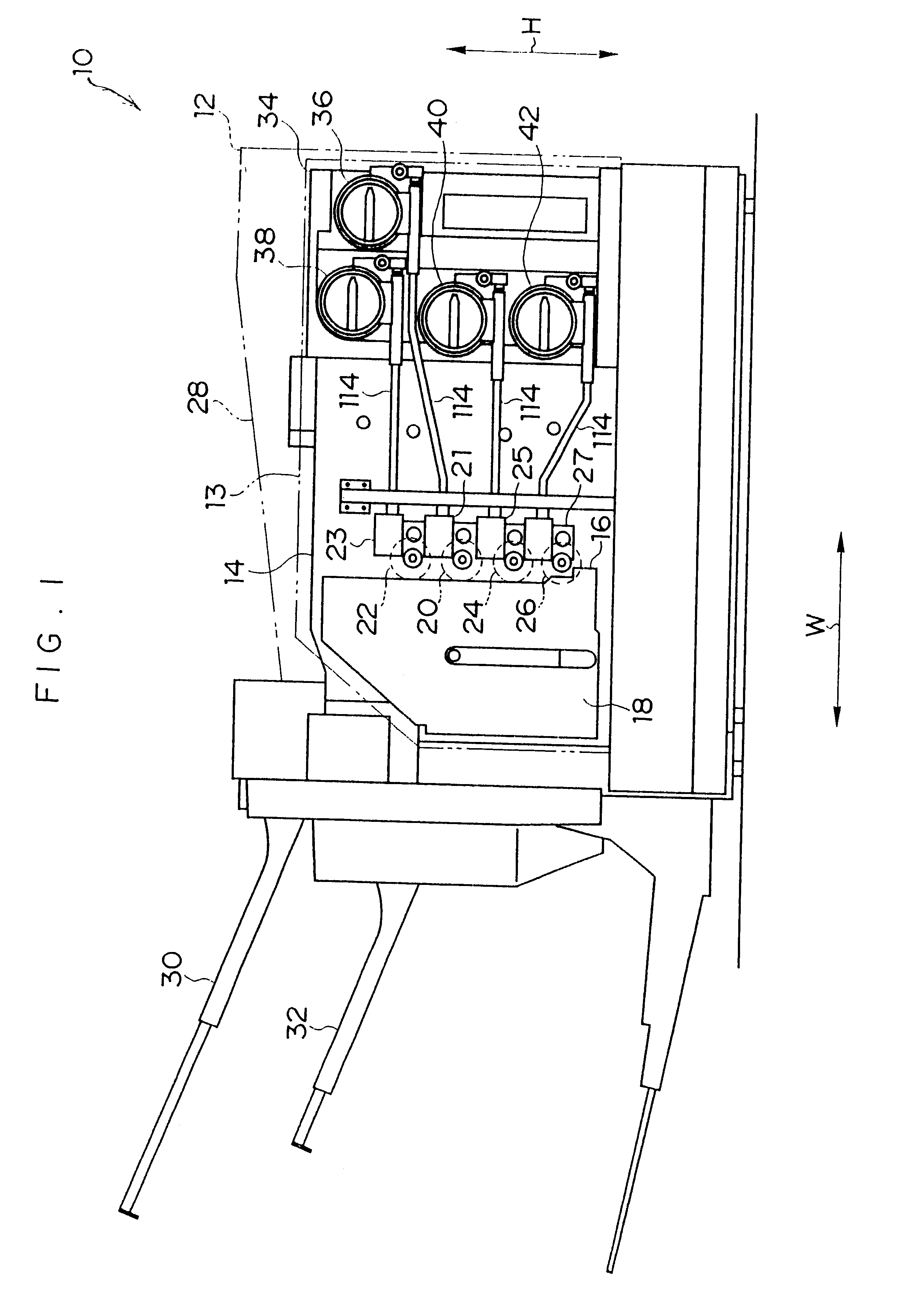
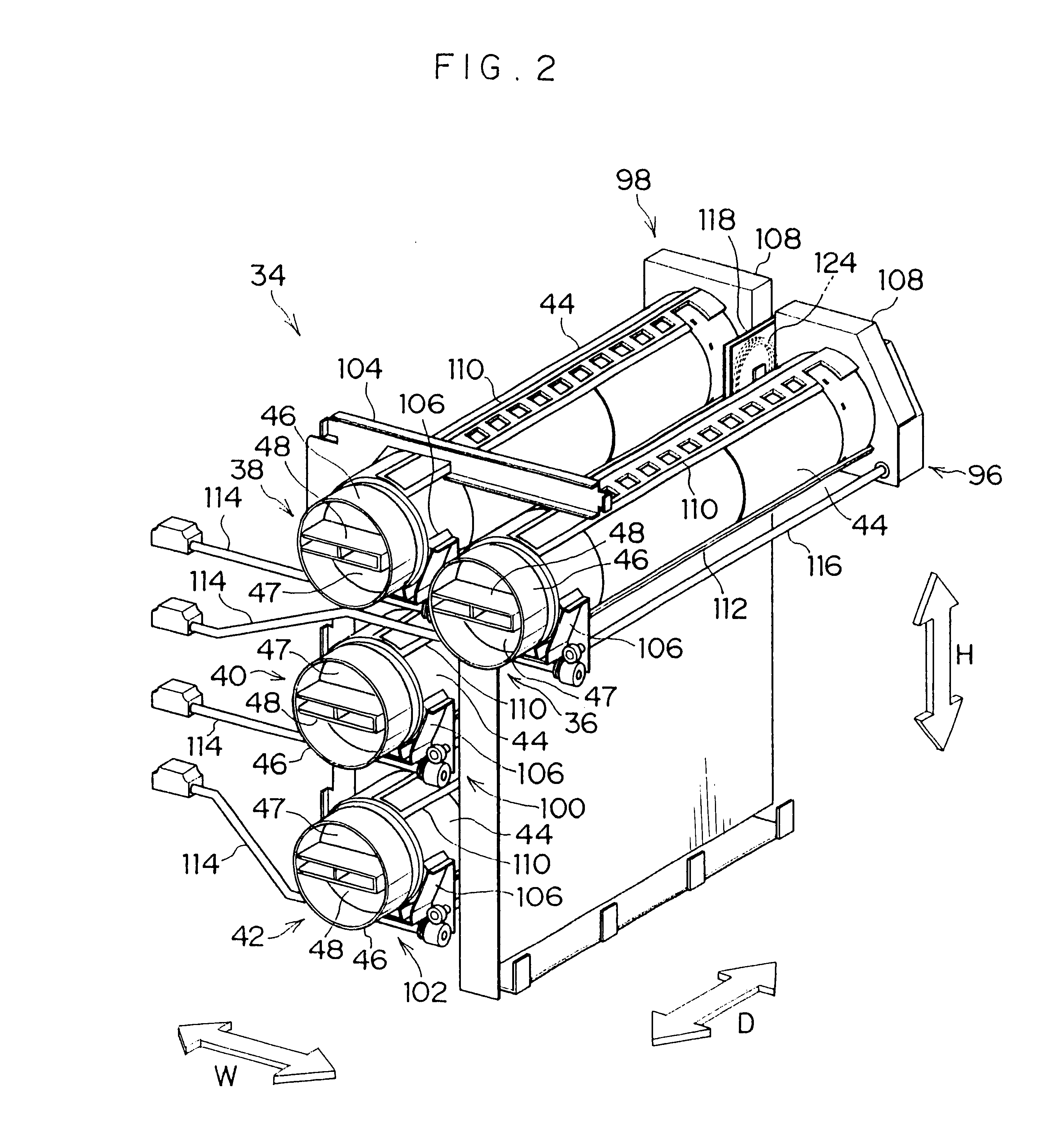
In a laser printer utilizing a wireless communication system 160 shown in FIG. 9, the four toner cartridges 36, 38, 40 and 42 accommodating M toner, Y toner, K toner and C toner, respectively, are detachably mounted at a cartridge holder 162. Also, a toner cartridge 172 accommodating K toner, which is usually consumed in the greatest amounts, is detachably mounted at the cartridge holder 162. Here, because there is a need to preserve mutual interchangeability of the toner cartridge 172 and the toner cartridge 40, the same data is written as the multi ID at each of the EEPROMs 142 of the wireless communication tags 72 attached at the toner cartridges 40 and 172.

As shown in FIG. 9, the five toner cartridges 36, 38, 40, 42 and 172 are mounted at the cartridge holder 162 so as to be arranged substantially in a straight line along a transverse dir...


PUM


Abstract

Tag side antennas attached at cartridge accessories and main body side antennas can be disposed sufficiently close to one another and facing one another without an increase in size of a device, even if the tag side antennas cannot be attached so as to cover end surface portions of the cartridge accessories and / or the number of the cartridge accessories mounted at the device main body is large. Tag side antennas disposed at each of toner cartridges are formed by conductive wiring in coil shapes. The toner cartridges are supported such that axes of these coils are substantially orthogonal to an insertion / removal direction at a cartridge holder. A main body side antenna is also formed by conductive wiring in a coil shape, has a coil axis substantially orthogonal to the insertion / removal direction, and may be supported interposed in a space between two of the toner cartridges.

Description

1. Field of the InventionThe present invention relates to a wireless communication system for use in various devices in which a plurality of cartridge accessories are detachably mounted at a device main body, and relates to an image forming device for a copier, facsimile machine, printer or the like in which a plurality of cartridge accessories are detachably mounted at a main body of the device.2. Description of the Related ArtIn order to facilitate maintenance in image forming devices such as copiers that use electrophotography processes, laser printers and the like, containers that accommodate toner are structured as toner cartridges. A toner cartridge is a cartridge accessory which is detachably mounted at a device main body. In such image forming devices, when all of the toner has been discharged from inside the toner cartridge, a user resupplies toner by replacing the toner cartridge with a new toner cartridge. At this time, the used toner cartridge which has been removed from...

Claims


Application Information

Patent Timeline
Patent Type & Authority Patents(United States)
IPC IPC(8): G03G21/18B41J29/00G03G15/08G03G21/00
CPCG03G21/1882G03G2221/1823G03G15/00
Inventor IIDA, ATSUSHISAITOU, KANOUSAKAI, HIROYUKI
Owner FUJIFILM BUSINESS INNOVATION CORP
Why Eureka
Try Eureka