
Objective manifest refraction

a manifest refraction and object technology, applied in the field of vision diagnostics, can solve the problems of expensive instruments, patient's perspective, subjective nature of the phoropter measurement process,

Inactive Publication Date: 2004-10-26
BAUSCH & LOMB INC
View PDF14 Cites 55 Cited by
  • Summary
  • Abstract
  • Description
  • Claims
  • Application Information

AI Technical Summary

Benefits of technology

In an embodiment of the invention, a method for providing an improved objective manifest refraction includes the steps of objectively obtaining diagnostic measurement data of a patient's eye that is indicative of at least fourth-order Zernike wavefront aberrations or their equivalents, and fitting a second-order only Zernike polynomial to the wavefront data to determine a simplified surface represented by the wavefront information obtained in the preceding step; and for calculating a manifest refraction value from the second-order surface calculation data that accurately corresponds to a subjective manifest refraction value. In various aspects, the wavefront measurement data will preferably include at least fifth and higher-order terms, up to seventh-order terms, and up to tenth-order terms. In an aspect of this embodiment, fitting the second-order Zernike polynomials to the higher-order wavefront data uses a least squares method. The objectively calculated refraction according to the invention (i.e., the predicted phoropter refraction, or PPR) is an accurate rendering of a patient's actual subjective refraction. An accurate PPR is one that is preferably within 0.75D to 0.5D of the patient's subjective refraction; more preferably within 0.5D to 0.25D; and most preferably less than a 0.25D difference from the patient's actual subjective refraction.
An advantageous offered by the invention is the ability for accurately specifying and prescribing a vision correction for lenses such as spectacle, intra-ocular, and contact lenses, for example, as well as for refractive surgical modification of the cornea, such as LASIK, LASEK, or PRK.

Problems solved by technology

The subjective nature of the phoropter measurement process, from the patient's perspective, is itself a disadvantage of this form of refractometry.
Practitioner error can also be problematic, especially when adequate practitioner training may be lacking as it often is in many underdeveloped areas of the world.
Although patient subjectivity has been removed from the measurement process, there are other disadvantages associated with autorefractors.
First, they are expensive instruments.
Second, autorefractor measurements are typically inaccurate, compared to a patient's subjective refraction.
There are reports of measurement errors in up to 20% of the population measured in this way.
Moreover, wavefront sensor data is not naturally indicative of manifest refraction.
Yet, as vision correction technology advances, wavefront sensing instrumentation will, by necessity, consume office space and resources.

Method used


Image

  • Objective manifest refraction
  • Objective manifest refraction
  • Objective manifest refraction

Examples


Embodiment Construction

An embodiment of the present invention is an improved method for providing an accurate manifest refraction value from an objective measurement procedure, preferably a wavefront measurement, which is not traditionally associated with providing manifest refraction values.

The measurement error (i.e., deviation from a subjective measurement value) commonly observed in autorefractor measurements is believed by some to be due at least in part to the presence of higher-order aberrations in the eye; i.e., optical error versus refractive (corneal) error. Without limitation to the invention described and claimed herein, this can be thought of as follows: optical aberrations such as, but not limited to, defocus, astigmatism, spherical aberration, and coma are described mathematically, for example, by Zernike polynomials and by other mathematical expressions. The Zernike polynomial equations include second-order, third-order, fourth-order, fifth-order, etc. terms wherein the second-order and lo...


PUM


Abstract

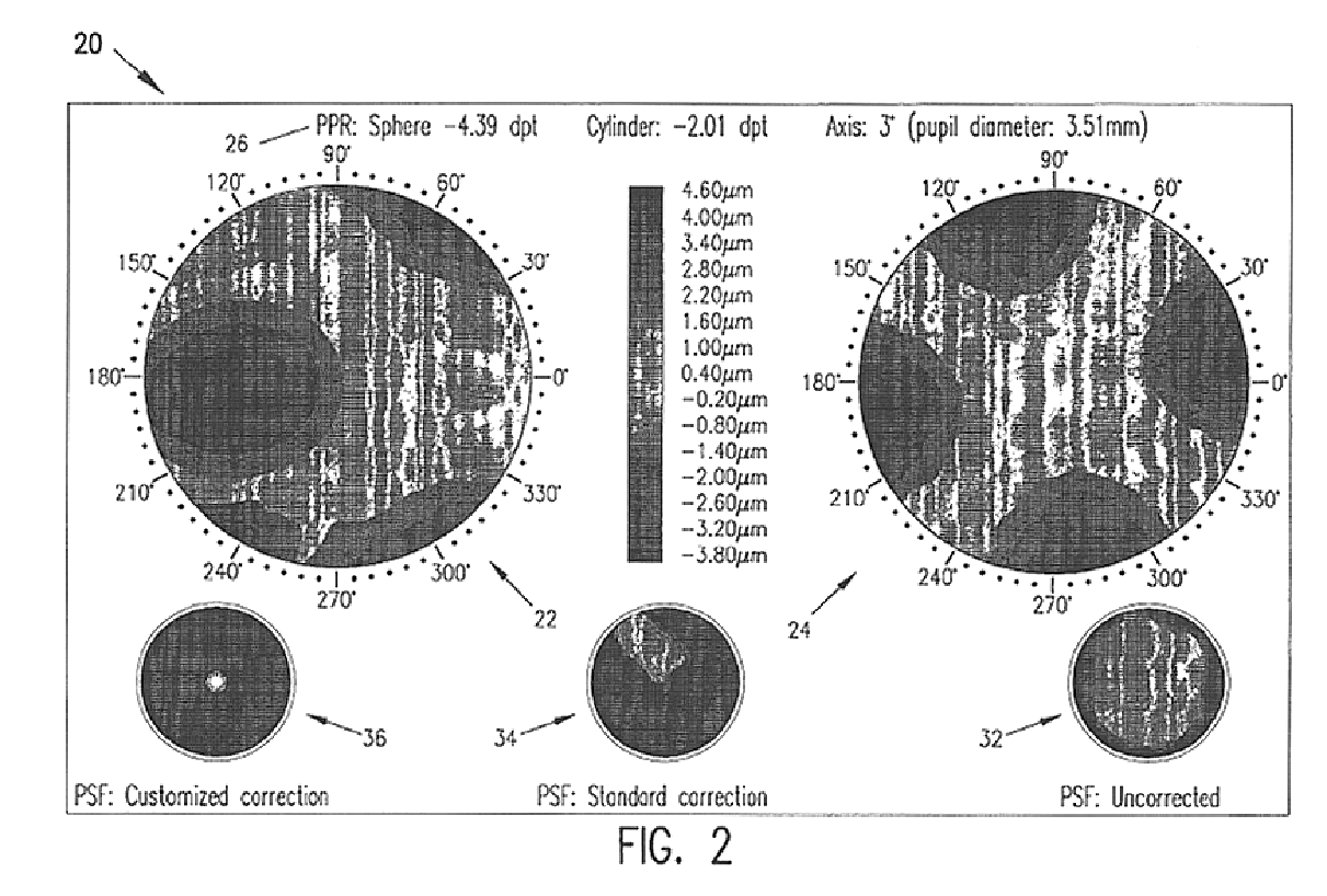
An method for providing an objective manifest refraction of a patient's eye includes obtaining at least fourth-order Zernike wavefront aberration information, fitting a second-order only polynomial to the at least fourth-order data, and using this information to predict the patient's manifest refraction with an accuracy approaching the patient's subjective manifest refraction. A method is also described for prescribing an accurate vision correction based upon the objective manifest refraction. A display according to the invention includes higher-order wavefront aberrations, lower order wavefront aberrations, numerical indicia of predicted manifest refraction, and images of qualitative assessments of a patient's vision quality. A device for obtaining an objective manifest refraction is described.

Description

1. Field of the InventionThe invention generally relates to vision diagnostics and, more particularly, to a method for providing improved objective manifest refraction values, an associated method for prescribing a vision correction, and apparatus associated therewith.2. Description of Related ArtA phoropter is a fundamental optometric diagnostic instrument for vision measurement and evaluation for obtaining a manifest refraction; i.e., defocus and astigmatism (often referred to as "lower-order" aberrations) in an undilated eye. It essentially is a device with a large set of lenses on dials. The device is positioned for a patient to look through and give visual acuity feedback to the practitioner when a particular dialed lens is presented in front of the patient's eye. This method of manifest refractometry provides defocus and astigmatism information to the practitioner typically in order to prescribe vision correcting lenses for the patient. The subjective nature of the phoropter m...

Claims


Application Information

Patent Timeline
Patent Type & Authority Patents(United States)
IPC IPC(8): A61B3/103A61B3/10
CPCA61B3/0025G16H50/30A61B3/103
Inventor YOUSSEFI, GERHARD
Owner BAUSCH & LOMB INC
Learn More