
Driver protection structure and a device supporting the same

a technology for protecting structures and drivers, applied in the direction of superstructure connections, superstructure subunits, loading-carrying vehicle superstructures, etc., can solve the problems of increasing manufacture and management costs, difficulty in repeatedly removing and mounting the driver protection structure, and insufficient strength

Inactive Publication Date: 2004-11-02
VOLVO CONSTR EQUIP HLDG SWEDEN AB
View PDF7 Cites 15 Cited by
  • Summary
  • Abstract
  • Description
  • Claims
  • Application Information

AI Technical Summary

Benefits of technology

"The present invention provides a driver protection structure and a device supporting the same that can be easily mounted over a driver's cabin and can withstand impacts from external objects. The driver protection structure is mounted over the driver's cabin and includes a roof protection structure and a front protection structure. The front protection structure is hinged to the roof protection structure and includes a gas spring to facilitate its openings and closings. The driver protection structure can be easily detached for wash front glass of the driver's cabin. The invention solves the problem of increased manufacture and management costs associated with conventional driver protection structures and also allows for easy removal and mounting of the driver protection structure based on work conditions."

Problems solved by technology

However, the above structure requires an upper frame for standard equipment and an upper frame for a driver protection structure, to thereby increase manufacture and management costs.
Further, there exist difficulties in repeatedly removing and mounting the driver protection structure according to work conditions.
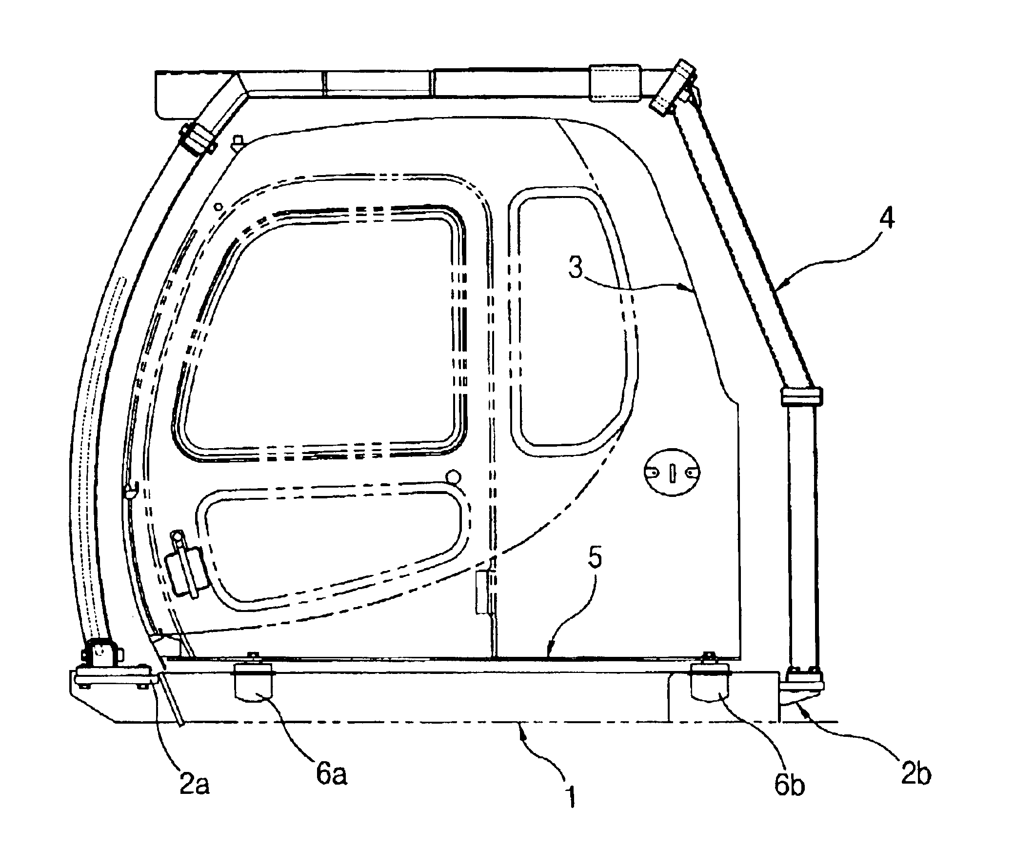
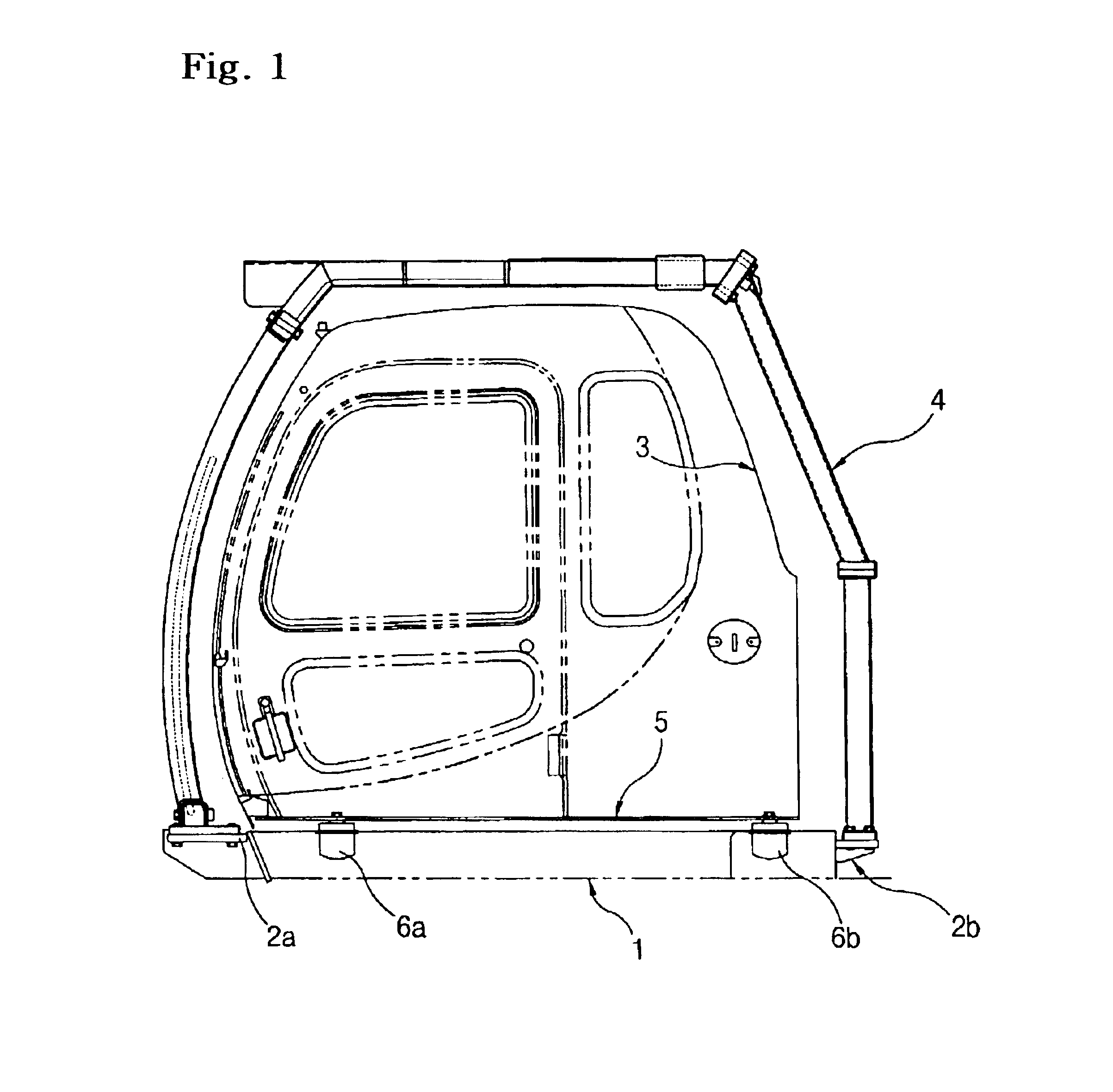
However, the vibration-absorbing devices 6a and 6b do not have the strength enough to absorb such a big load, which causes a problem the driver protection structures 4a and 4b can not be directly installed over the driver's cabin 3.

Method used


Image

  • Driver protection structure and a device supporting the same
  • Driver protection structure and a device supporting the same
  • Driver protection structure and a device supporting the same

Examples


Embodiment Construction

Hereinafter, a preferred embodiment of the present invention is described in detail with reference to the accompanying drawings, which does not mean defining the technical spirit and scope of the present invention but is for explaining in detail the present invention in order for one skilled in the art to which the present invention pertains to implement the present invention.

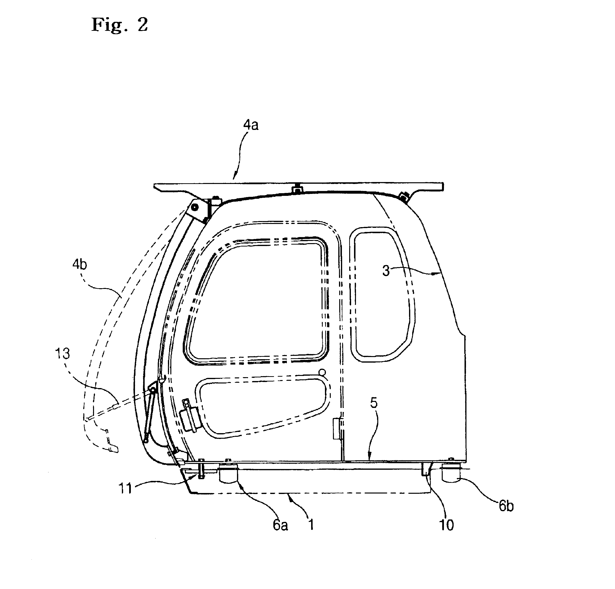
As shown in FIG. 2, an upper side of heavy equipment having a driver protection structure mounted over a driver's cabin and a device supporting the same according to an embodiment of the present invention includes an upper frame 1 mounted on a lower traveling body(not shown), a driver's cabin 3 mounted on the upper frame 1, vibration-absorbing devices 6a and 6b mounted between the upper frame 1 and a bottom plate 5 of the driver's cabin 3, driver protection structures 4a and 4b mounted over the driver's cabin 3 of heavy equipment capable of securing driver's safety, and a supporting device having a first stoppe...


PUM


Abstract

The present invention relates to a driver protection structure and a device supporting the same which secure driver's safety according to the international standardization organization when collided with a falling object and upon equipment's rollovers, comprising a first stopper which allows a driver's cabin and the driver protection structure mounted over the driver's cabin to move in a vertical direction and restricts the driver's cabin to move in a horizontal direction, and a second stopper which allows the driver's cabin to move in the vertical direction and restricts the driver's cabin to be lifted when a load is applied to the driver's cabin from external.

Description

1. Field of the InventionThe present invention relates to a driver protection structure and a device supporting the same which are mounted outside a driver's cabin to enable driver's safety to be secured in case that an object falls toward the driver's cabin from outside or equipment is rolled over, and more particularly to a driver protection structure coupled in one body with the driver's cabin and to a support device overcoming an impact transferred to the driver protection structure.2. Description of Prior ArtAccording to the International Standardization Organization(ISO), a driver protection structure mounted outside a driver's cabin of heavy equipment includes a falling-over protective structure(FOPS) preventing falling objects from being invaded within a range of driver's work in order to protect a driver, and a roll-over protective structure protecting a driver in case that equipment is rolled over.FIG. 1 is a view for schematically showing an upper side of heavy equipment ...

Claims


Application Information

Patent Timeline
Patent Type & Authority Patents(United States)
IPC IPC(8): B60R21/13B60R21/11B62D33/06B60R21/02B60R21/00E02F9/16B62D25/06B62D25/08B62D27/04
CPCB60R21/11B60R21/13E02F9/163B62D33/0617B60R2021/0074B62D33/06
Inventor JO, CHUN HOYOON, CHUN JIN
Owner VOLVO CONSTR EQUIP HLDG SWEDEN AB
Learn More