Garbage bin with air cleaner

a technology of air cleaner and garbage bin, which is applied in the field of garbage bins, can solve the problems of kitchen waste smelling soon, and achieve the effect of removing odor

Inactive Publication Date: 2004-11-09
LIN TSONG YOW
View PDF11 Cites 70 Cited by
  • Summary
  • Abstract
  • Description
  • Claims
  • Application Information

AI Technical Summary

Benefits of technology

It is the primary objective of the present invention to provide a garbage storage apparatus for eliminating odor.

Problems solved by technology

However, the kitchen waste tends to stink soon after it is put in one of the bags 3.

Method used


Image

  • Garbage bin with air cleaner
  • Garbage bin with air cleaner
  • Garbage bin with air cleaner

Examples


first embodiment

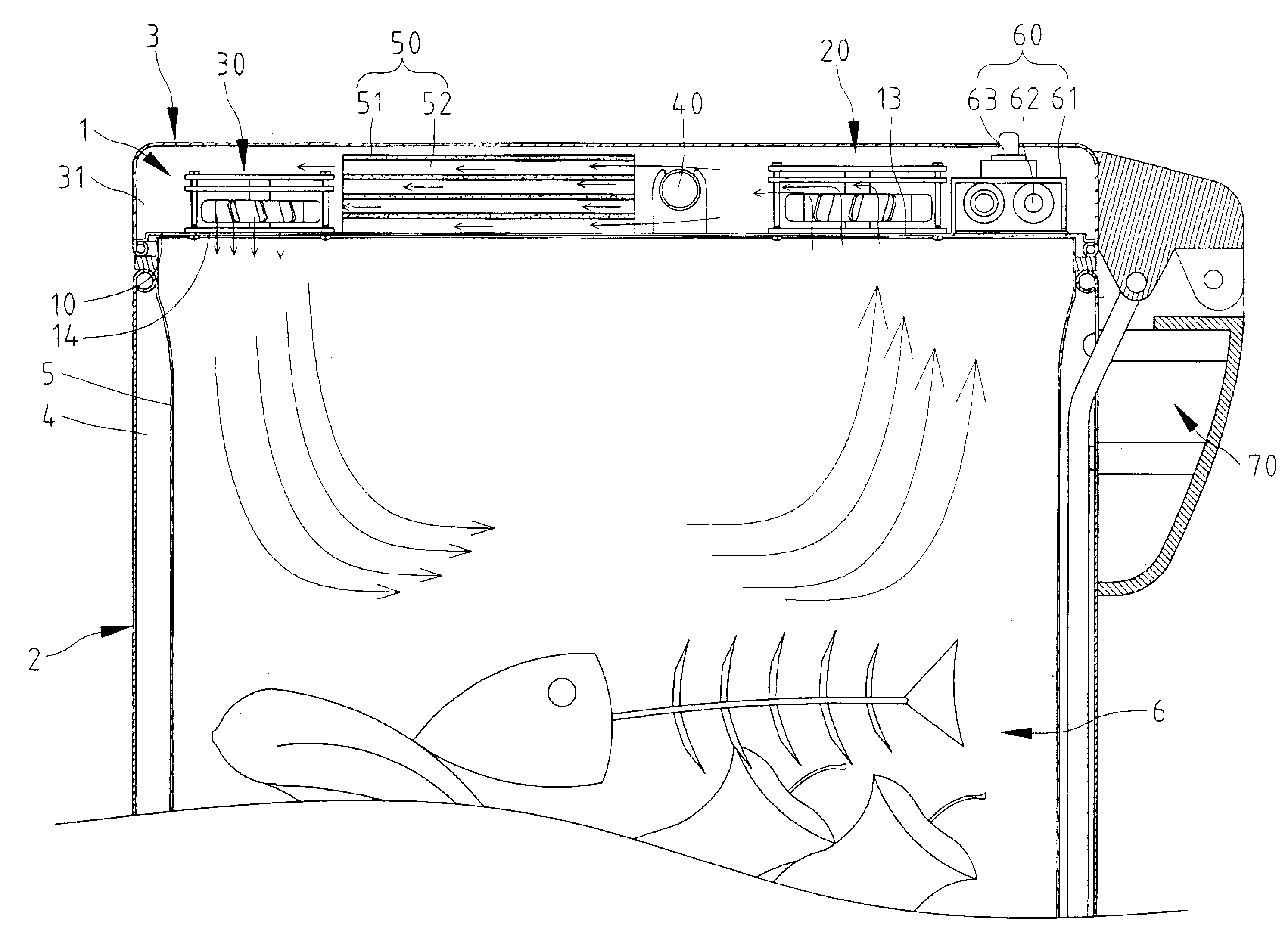
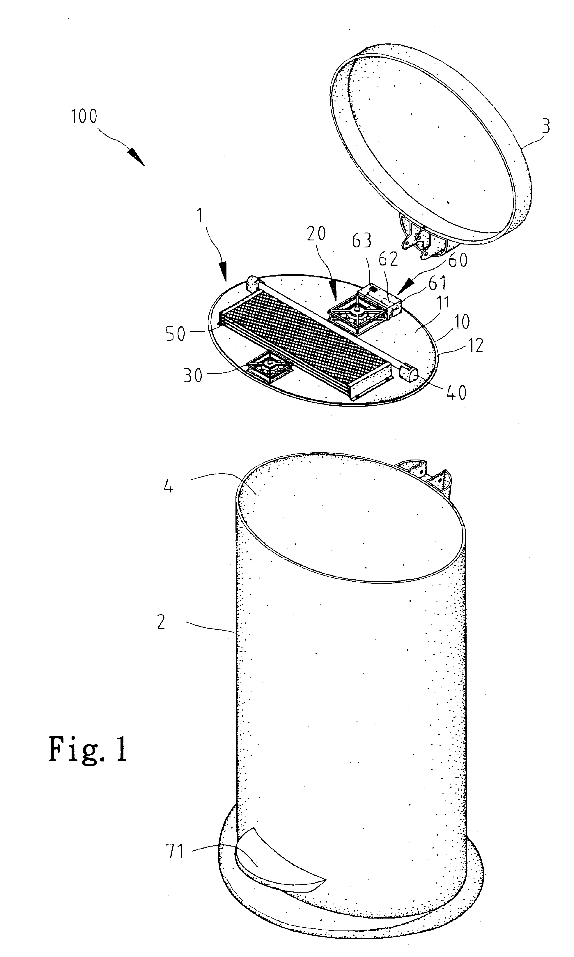
Referring to FIGS. 1-5, according to the present invention, a garbage storage apparatus 100 includes a bin 2, a cover 3 pivotally mounted on the bin 2 by a hinge 70 and an air cleaner 1 communicated with the bin 2.

The bin 2 defines a space 4 for receiving garbage 6. In the first embodiment, an internal bin 5 is installed in the space 4. Garbage 6 is to be stored in the internal bin 5. However, the internal bin 5 is optional and can be saved.

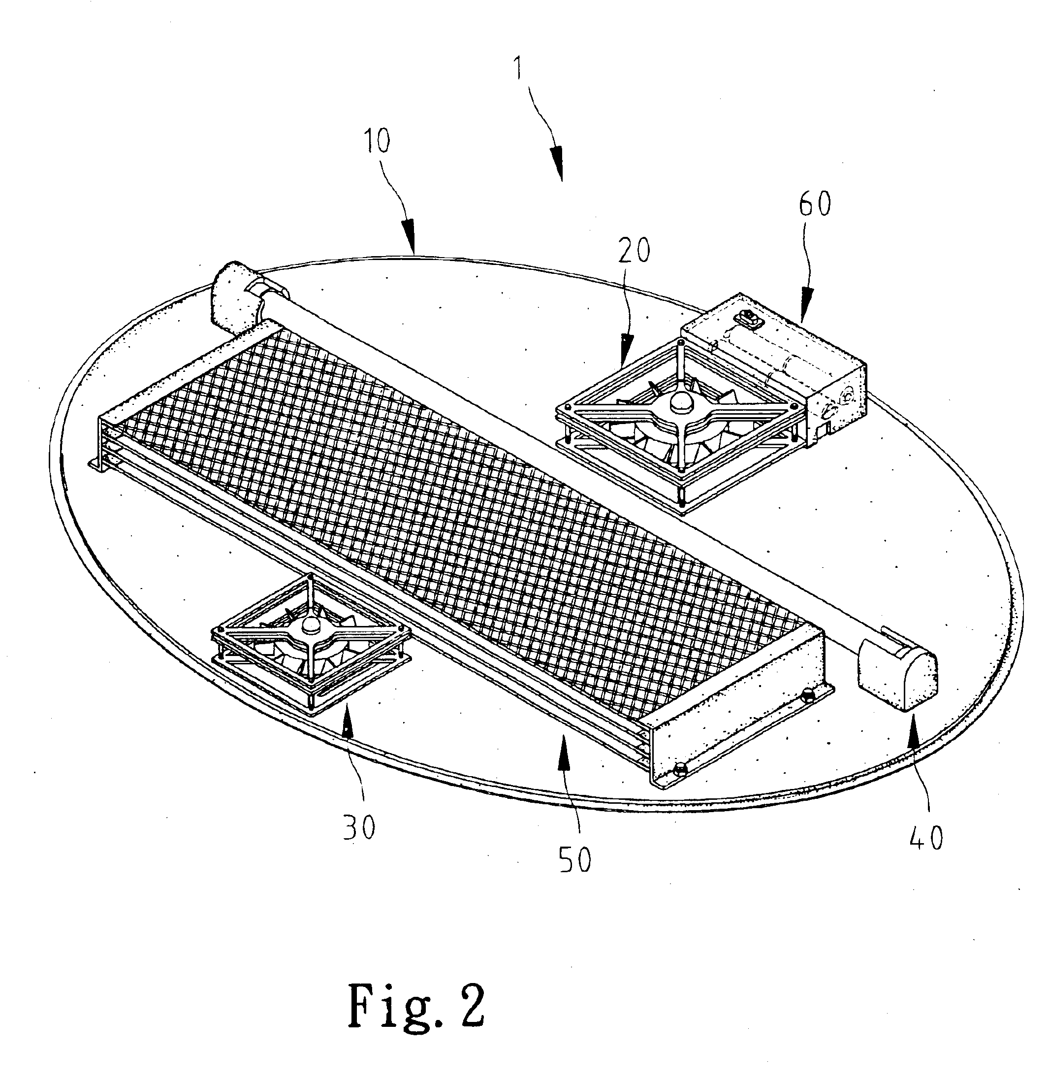
The air cleaner 1 includes a support 10, a first fan 20 mounted on the support 10, a second fan 30 mounted on the support 10, a light source 40, an optical catalyst 50 and a power supply 60.

Referring to FIG. 3, the support 10 is in the form of a disc with an upper face 11 for supporting the first fan 20, the second fan 30, the light source 40, the optical catalyst 50 and the power supply 60 and with an edge 12 for engagement with an edge of the cover 3. The support 10 defines a first group of slots 13 and a second group of slots 14.

The first fan ...

second embodiment

FIG. 6 shows a garbage storage apparatus according to the present invention. The second embodiment differs from the first embodiment in using an AC power supply 60' instead of the DC power supply 60. The AC power supply 60' includes a box 61, a switch 63 installed on the box 61, a circuit board 64 installed in the box 61, a wire 65 leading from the circuit board 64 and a plug 66 formed at an end of the wire 65.

third embodiment

FIG. 7 shows a garbage storage apparatus according to the present invention. The third embodiment differs from the first embodiment in two aspects. Firstly, the light source 40 is saved. To activate the optical catalyst 50, a window 41 is installed on the cover 3 so that light can shine on the optical catalyst 50 through the window 41. Secondly, the second fan 30 is saved.


PUM

PropertyMeasurementUnit
AC poweraaaaaaaaaa
DC poweraaaaaaaaaa

Abstract

A garbage storage apparatus includes a bin, a cover and an air cleaner. The bin defines a space for storing garbage. The cover is for covering the bin. The air cleaner is communicated with the bin for cleaning air in the bin. The air cleaner may include a catalyst for processing the air. The catalyst may be an optical catalyst that is activated by light.

Description

BACKGROUND OF INVENTIONThe present invention relates to a garbage bin capable of cleaning air.Related Prior ArtTaiwanese Patent Publication No. 483430 discloses a conventional garbage storage apparatus for storing two sorts of garbage. This conventional garbage storage apparatus includes a bin 1 and a holder 2 for holding two bags 3 in the bin 1. The bin 1 includes an upper edge 12 defining an opening. The holder 2 includes a lever 21 and two frames 22. The lever 21 is mounted on an upper edge 12 so as to divide the opening defined in the upper edge 12 into two sub-openings. Bach of the bags 3 is put in the bin 1 through one of the sub-openings. Each of the frames 22 is put in an upper edge of one of the bags 3 and then mounted on the upper edge of the bin 1 and the lever 21. Thus, each of the bags 3 is retained open for taking a type of garbage. In use, one of the bags 3 may store kitchen waste and the other one of the bags 3 other garbage, for example. However, the kitchen waste t...

Claims


Application Information

Patent Timeline
Patent Type & Authority Patents(United States)
IPC IPC(8): B65F1/16B65F7/00B65F1/00B65F1/14
CPCB65F1/163B65F7/00B65F2210/137
Inventor LIN, TSONG-YOW
Owner LIN TSONG YOW
Why Eureka
Try Eureka