Rear projector

a projector and rear-facing technology, applied in the field of rear-facing projectors, can solve the problems of generating dispersion, affecting determining the limit of the display position of images,

Inactive Publication Date: 2004-11-09
SEIKO EPSON CORP
View PDF15 Cites 26 Cited by
  • Summary
  • Abstract
  • Description
  • Claims
  • Application Information

AI Technical Summary

Benefits of technology

In the above aspect of the present invention, the support plate is provided on the casing and the image generator is located on the support base having a support surface slanted relative to the support plate, where the inclination position adjusting mechanism is provided on the support base. The attitude of the image generator projecting the generated optical image is adjusted by the inclination position adjusting mechanism. Accordingly, distortion of the image displayed on the screen can be optimized by adjusting the attitude thereof and the undisplayable area of the image projected on the screen can be narrowed in adjusting the position of the image projected and displayed on the screen by the image generator. Accordingly, even when the aspect ratio of the displayed image changes according to difference in tolerance of the configuration of the casing of the rear projector and tolerance of the components installed in the casing and dispersion is caused on the image displayed on the screen, optimization is possible by adjusting the attitude of the image generator by the inclination position adjusting mechanism, thus displaying the image on the entire screen.
Accordingly, the end of the reflection optical system can be received by the elastic deformation of the elastic member in accordance with inclination of the reflection optical system, thereby avoiding restriction of the inclination of the reflection optical system by the fixed holder.

Problems solved by technology

However, when such simple position adjuster where the position of the projection lens is horizontally or vertically adjusted is used for adjusting the position of the image, there is certain limit capable of adjusting the display position of the image and undisplayable area for displaying the image is formed on the screen even after adjusting the position of the projection lens.
Further, there is difference in the tolerance of the profile of the casing of the rear projector and the tolerance of the component installed in the casing, the tolerance causing difference in aspect ratio of the displayed image, so that the projection dispersion is generated on the image displayed on the screen.
However, since undisplayable area is formed by the conventional divisional display position adjuster, the image cannot be displayed on the entire screen and, when large undisplayable area is formed, the displayed image runs off the edge of the screen and only the image displayed within the frame of the screen can be recognized by a viewer.
Normally, the casing that houses the image generator, the reflection optical system and the screen is formed by injection molding etc., and slight dimension tolerance is inevitably caused in such casing.

Method used


Image

  • Rear projector
  • Rear projector
  • Rear projector

Examples


first embodiment

1-7. Effect of First Embodiment

According to the above-described embodiment, following advantages can be obtained.

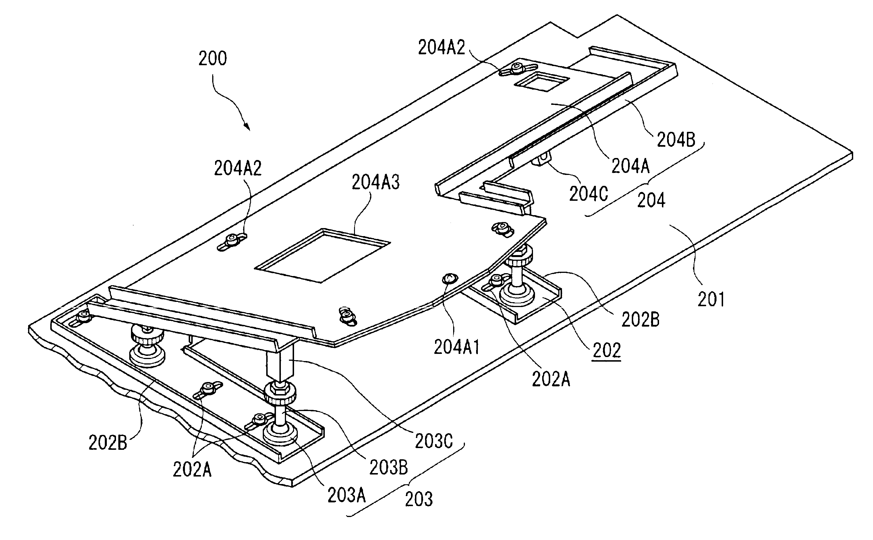
(1) Since the optical unit is provided with the support member 200 having a lateral position adjuster 202, an inclination adjuster 203 and the rotary position adjuster 204, the attitude of the optical unit for projecting the image can be adjusted by three axes. Accordingly, undisplayable area of the projected image to the screen can be narrowed in adjusting the display position of the image projected by the optical unit on the screen.

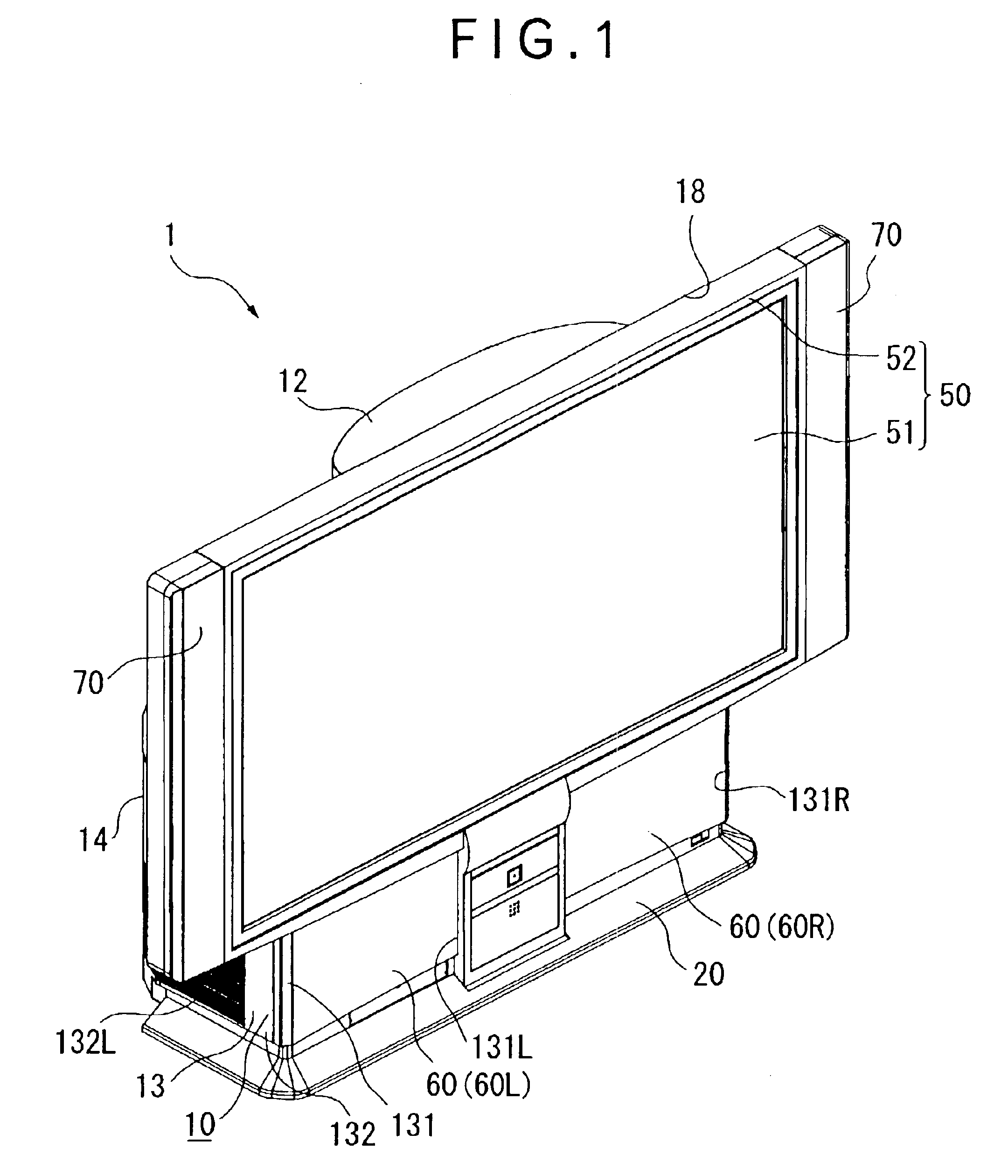
Therefore, even when aspect ratio of the displayed image is changed due to difference in the tolerance of the cabinet 10 of the rear projector 1 and the tolerance of the components installed in the cabinet 10 to cause projection dispersion on the image displayed on the screen, optimization is possible by adjusting the attitude of the optical unit body 401A by the support member 200, thereby displaying the image on the entire screen.

(2) Since ...

second embodiment

2-2. Effect of Second Embodiment

According to the above second embodiment, following advantages can be obtained as well as substantially identical advantages of the above (1), (2), (4) to (8) and (12) to (20).

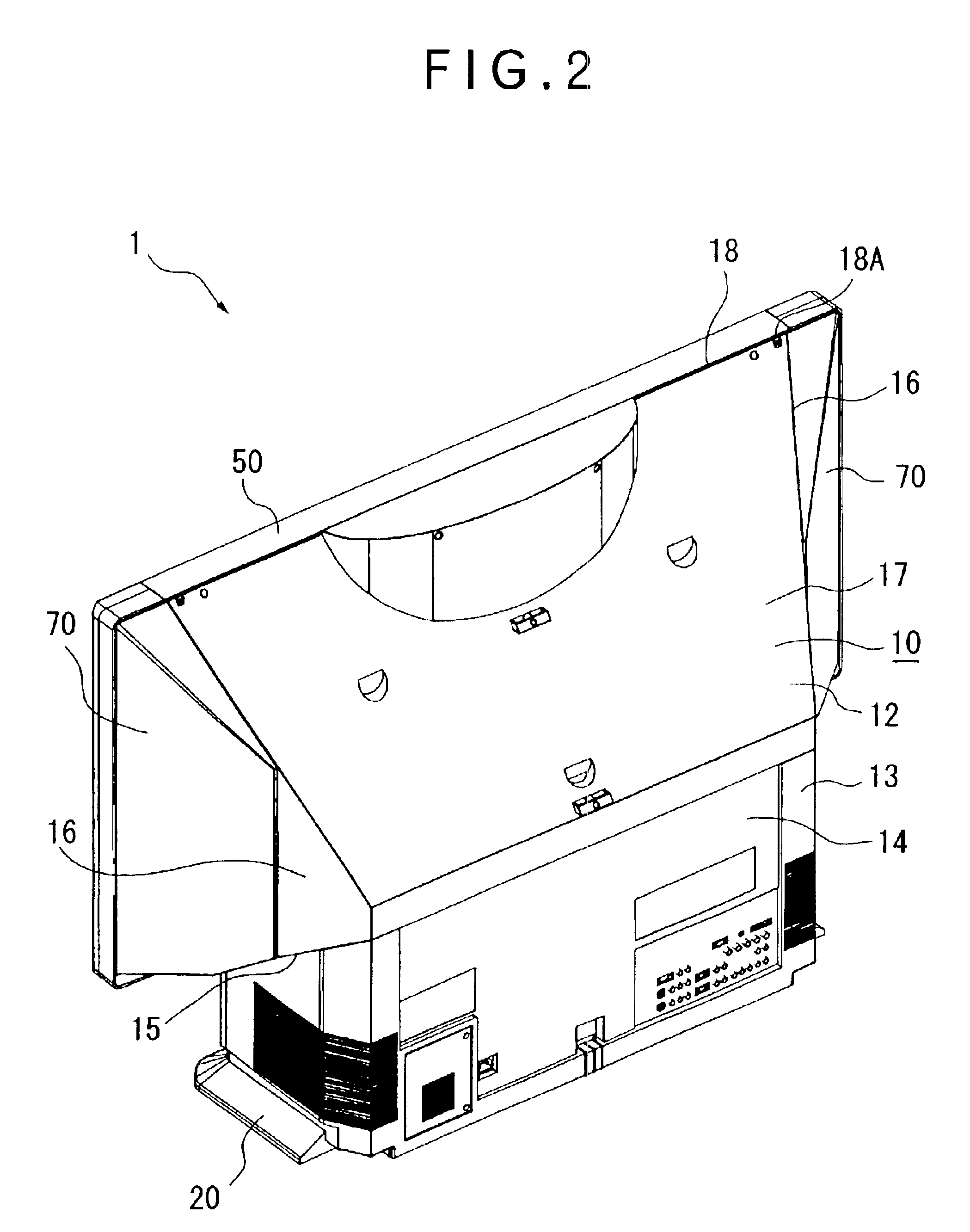
(21) The optical unit 401 and the power source block 300 are located between the base member 201 and the rotary position adjuster 204 and are isolated in the lower cabinet 13 from the other components such as the screen 51 by the base member 201 and the rotary position adjuster 204. Accordingly, the base member 201 and the rotary position adjuster 204 work as a duct for guiding the cooling air in the internal cooling mechanism 500, thereby efficiently cooling the components in the optical unit 401 and the power source block 300. Further, since the cooling air circulates along the base member 201 and the rotary position adjuster 204, the base member 201 and the rotary position adjuster 204 can also work as a component for insulating heat to the screen 51 disposed in the upper cab...


PUM


Abstract

In order to provide a rear projector capable of facilitating position adjustment of an image displayed on a screen and optimizing dispersion of the aspect ratio of the projected image caused by tolerance of components by adjusting the position of the image, a support member (200) is provided with a lateral position adjuster (202) as a planar position adjusting mechanism attached on a support plate of an interior unit in an opposing manner, an inclination adjuster (203) as an inclination position adjusting mechanism vertically provided on the lateral position adjuster (202), and a rotary position adjuster (204) as a rotary position adjusting mechanism attached to the inclination adjuster (203) slanted downward toward rear side.

Description

1. Field of the InventionThe present invention relates to a rear projector that displays image on a transmissive screen.2. Description of Related ArtConventionally, a rear projector that displays a projected and enlarged image on a screen is known as a large-screen display device.In such rear projector, the light beam from a light source is irradiated on a transmissive liquid crystal panel, where the light beam is modulated in accordance with image information by the transmissive liquid crystal panel, and is enlarged by a projection lens, of which optical path is changed by a reflection mirror to be introduced to a rear side of a screen.According to the above arrangement, all of the components can be housed in a movable casing and the image on the screen can be viewed in a well-lighted room.In order to adjust the position of the image displayed on the screen, a position adjuster, which normally adjusts the position of the projection lens in horizontal or vertical position, is necess...

Claims


Application Information

Patent Timeline
Patent Type & Authority Patents(United States)
IPC IPC(8): G03B21/22G03B21/00G03B21/10G03B21/54G03B21/14H04N5/64H04N5/74
CPCG03B21/22G03B21/145G03B21/62G03B21/10H04N5/74
Inventor YAMADA, HARUYOSHIARAI, JUN
Owner SEIKO EPSON CORP
Why Eureka
Try Eureka