Insert holder for parting and grooving operations

a cutting tool and inserting holder technology, applied in the direction of cutting inserts, manufacturing tools, shaping cutters, etc., can solve the problems of inability to determine the clamping force of the cutting insert, the unsatisfactory accessibility of the tightening screw, and the difficulty of inserting and manipulating the key in the limited space between neighboring tools

Inactive Publication Date: 2004-11-09
SANDVIK INTELLECTUAL PROPERTY AB
View PDF7 Cites 31 Cited by
  • Summary
  • Abstract
  • Description
  • Claims
  • Application Information

AI Technical Summary

Benefits of technology

The present invention aims at obviating the above-mentioned disadvantages of previously known cutting tools for parting and grooving operations and at providing an improved cutting tool of this type. Therefore, a primary aim of the invention is to provide a cutting tool, the clamping mechanism of which is conveniently accessible for a key or the like also in such cases when a plurality of tools are mounted near each other. An additional aim is to create a cutting tool, the clamping mechanism of which should be structurally simple and which works in a reliable manner, whereby the correct clamping force on the cutting insert is obtained in a simple manner, more precisely without the operator needing to devote mental effort to this problem in connection with the continuous repetitive change of cutting inserts.

Problems solved by technology

This entails problems in such applications where it is desirable to mount a plurality of cutting tools close to each other in the same plane so far that it becomes difficult to insert and manipulate a key in the limited space between neighboring tools.
The disadvantages of the unsatisfactory accessibility of the tightening screws become particularly apparent with small cutting tools of the type called "Swiss Tools."
Another disadvantage of the previously known cutting tools is that the tightening torque of the tightening screw, and thereby the clamping force of the cutting insert, cannot be determined in any well-defined way.

Method used


Image

  • Insert holder for parting and grooving operations
  • Insert holder for parting and grooving operations
  • Insert holder for parting and grooving operations

Examples


Embodiment Construction

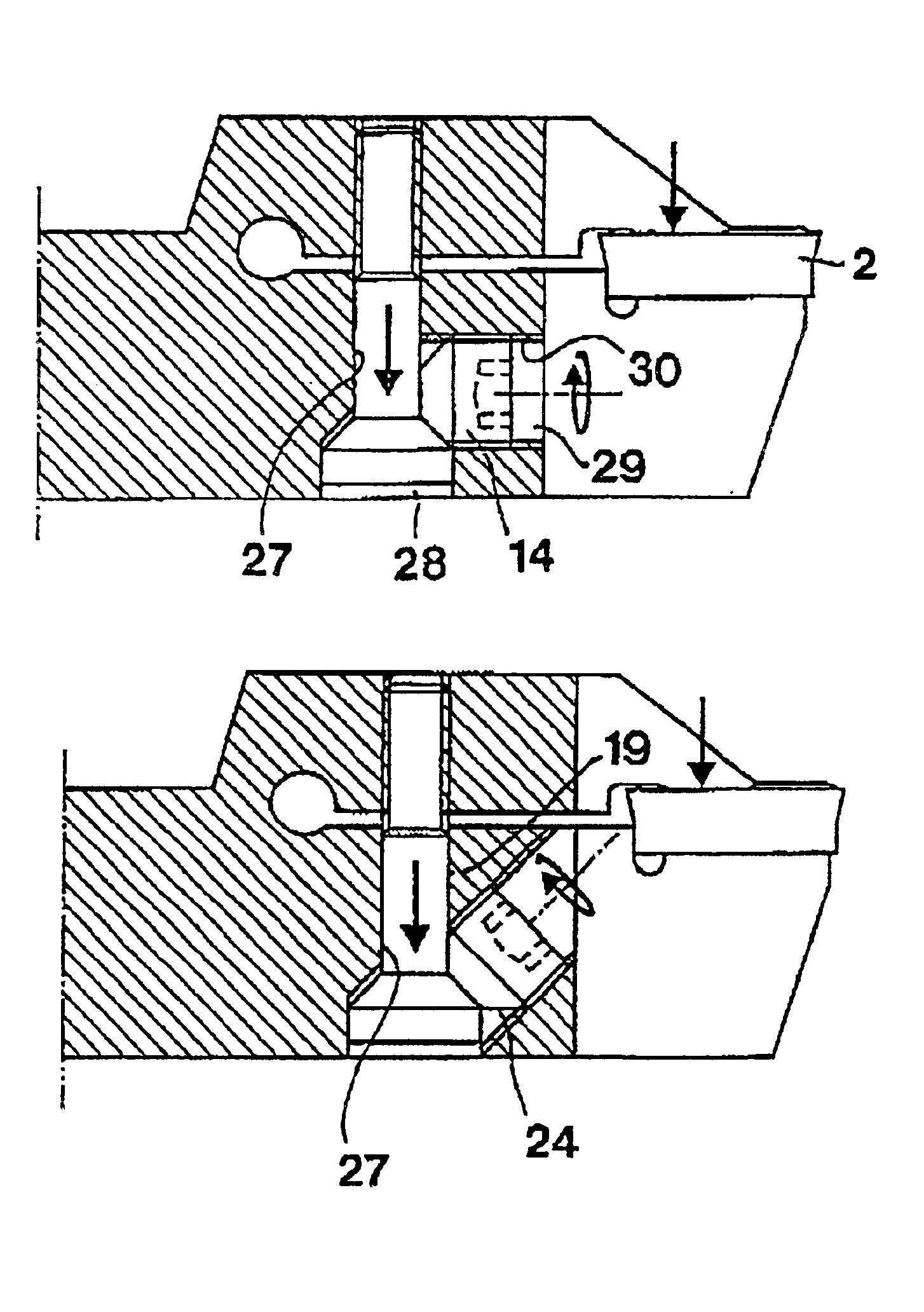
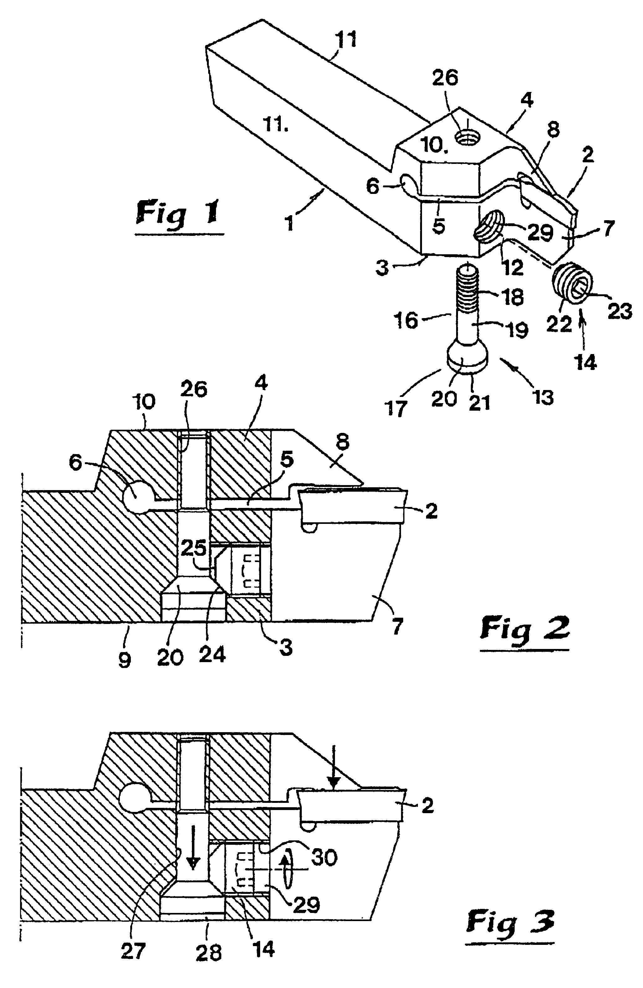
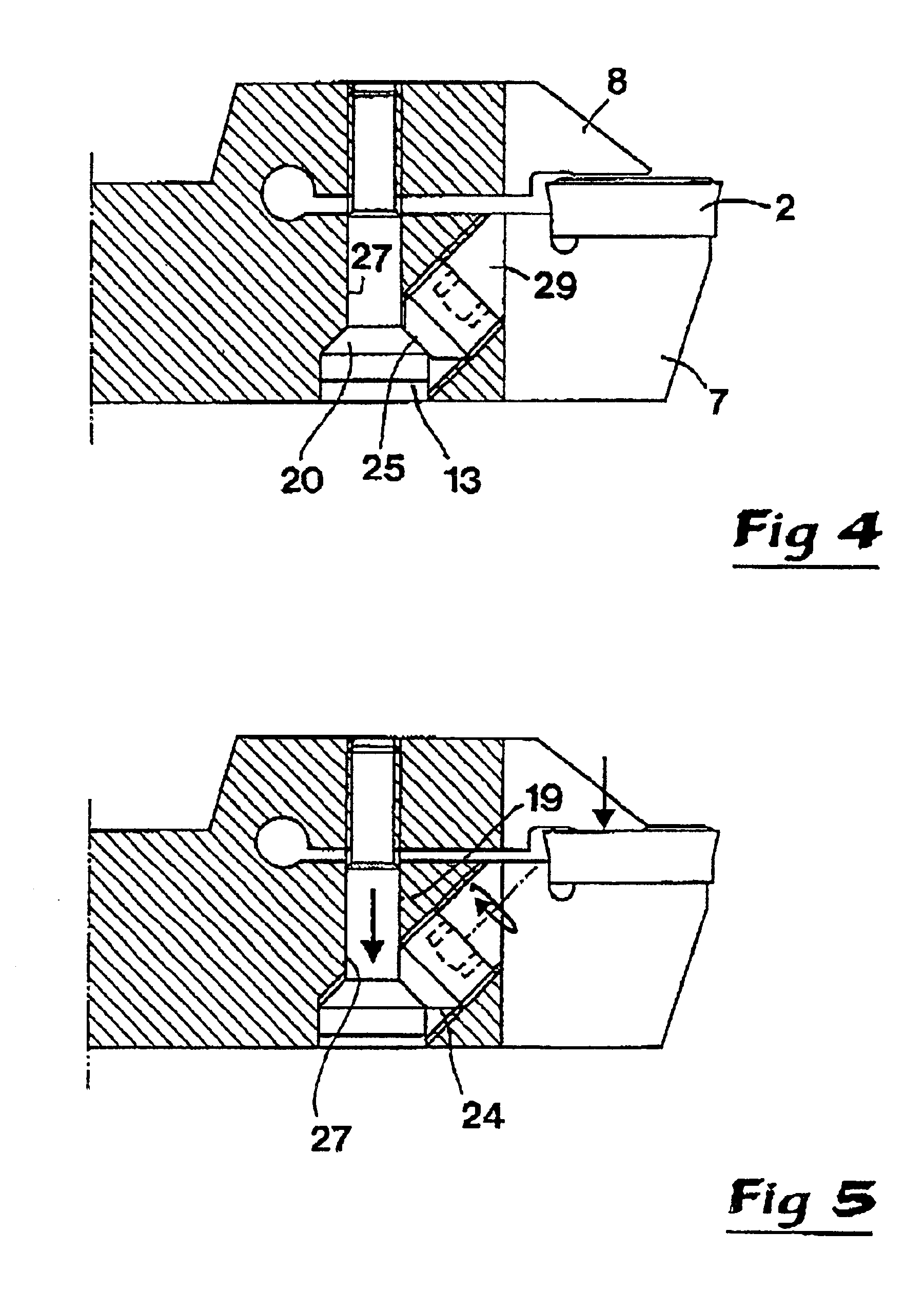
In FIGS. 1-3, a cutting tool is shown including a holder 1 and a cutting insert 2. In this example, the holder 1 comprises a body having the shape of a long narrow shaft, with a quadrangular cross-section shape, which at a front end is formed with lower and upper front parts 3 and 4, respectively. Said front parts 3, 4 are spaced-apart by a gap 5 which at the back transforms into a cylindrical through cavity 6. The holder 1 is, in its entirety, manufactured from steel or other material having a certain inherent elasticity. Thanks to the existence of the gap 5, the front parts 3, 4 may be brought to swivel in relation to each other. A so-called blade tongue extends from the lower front part 3. A clamping finger 8 extends from the upper front part 4 in overlying, spaced relationship to the tongue 7. Together, the blade tongue 7 and the clamping finger 8 define a jaw-like seat in which the cutting insert 2 may be assembled and clamped. In practice, the blade tongue 7 and the clamping f...


PUM

PropertyMeasurementUnit
thicknessaaaaaaaaaa
cone angleaaaaaaaaaa

Abstract

A holder is designed to receive a cutting insert intended for parting and grooving operations. The insert is clampable in a seat formed between a blade tongue and a clamping finger which respectively extend from lower and upper front parts of the holder. A gap separates those front parts in order to enable those parts to be forced towards each other by means of a clamping mechanism mounted in the holder. The clamping mechanism comprises a drawbar, a first end portion of which is movable within a bore formed in one of the front parts, and a second end portion of which is fixed in the other front part. The first end portion of the drawbar includes a head having a frusto-conical abutment surface. A tightening screw is threadedly mounted in the same front part as the head and is arranged to contact the abutment surface to displace the drawbar in a direction forcing the clamping finger and the tongue together to clamp the cutting insert in place.

Description

This application claims priority under 35 U.S.C. .sctn..sctn.119 and / or 365 to Patent Application Serial No. 0101419-0 filed in Sweden on Apr. 24, 2001, the entire content of which is hereby incorporated by reference.1. Technical Field of the FieldThis invention relates to a cutting tool intended for parting and grooving operations of the type that comprises a holder for a narrow cutting insert which is clampable in a seat between a blade tongue and a clamping finger protruding as extensions of the lower and upper front parts of the holder. The front parts are thicker than the blade tongue and the clamping finger and are spaced-apart by a gap which enables swivelling of the front parts--and thereby also the blade tongue and clamping finger, respectively, in a direction towards each other from a starting position, more precisely by means of a clamping mechanism mounted in the holder.2. Prior ArtCutting tools of the above-mentioned type are used for grooving, parting, or other operati...

Claims


Application Information

Patent Timeline
Patent Type & Authority Patents(United States)
IPC IPC(8): B23B27/00B23B27/04B23B27/16
CPCB23B27/04B23B29/043Y10T407/25Y10T407/2288Y10T407/2282B23B2205/02B23B27/16
Inventor SHIRAIWA, AKIOHANSSON, PER
Owner SANDVIK INTELLECTUAL PROPERTY AB
Why Eureka
Try Eureka