Resectoscope

a technology of resectoscope and suction tube, which is applied in the field of resectoscope, can solve the problems of reducing the patient's comfort,

Inactive Publication Date: 2004-11-30
RICHARD WOLF GMBH
View PDF15 Cites 73 Cited by
  • Summary
  • Abstract
  • Description
  • Claims
  • Application Information

AI Technical Summary

Benefits of technology

Preferably at the distal end of the resectoscope, i.e. at the end proximal to the patient there is provided a cutter loop which delimits a cross sectional area which in its dimension is smaller or equal to the cross sectional area of the suction channel. The cutter loop serves for detaching tissue parts, as with known resectoscopes. For this the cutter loop is preferably designed as a U-shaped bow which is led through the tissue. The cross sectional area delimited by the cutter loop is determined by the loop size. The size of a detached tissue part or chip is defined by selection of the loop size. Since the loop size is selected such that the cross sectional area delimited by the cutter loop is smaller or equal to the cross sectional area of the suction channel, one may ensure that the detached chips have a size which is smaller than the cross section of the suction channel so that the chips may be safely led away through the suction channel. One may thus prevent the detached chips from sticking in the suction channel and blocking this.
Preferably the valve is designed as a magnet valve which is activated by an electrical actuation signal. The electrical activation of the valve permits a very variable and simple adjustment of the opening duration of the valve. The magnet valve is preferably designed as a flexible tubing squeezer which clamps a suction flexible tubing. The clamping is released on opening the magnet valve so that fluid may flow through the suction flexible tubing in the direction of the vacuum source in order to be able to suction fluid and detached chips out of the body cavity.

Problems solved by technology

This manner of proceeding is relatively time-consuming and is thus a burden to the patient.
This leads to a narrowing of the suction channel; furthermore there exists the danger that tissue parts to be suctioned catch on the actuation elements for the cutter loop.
The arrangement of flexible tubings between the first valve and the suction channel with an impulsed suctioning has the disadvantage that on opening the first valve a vacuum prevailing at this leads to an elastic deformation, i.e. to a narrowing of the cross section of the flexible tubing between the valve and the suction channel.

Method used


Image

  • Resectoscope
  • Resectoscope
  • Resectoscope

Examples


Embodiment Construction

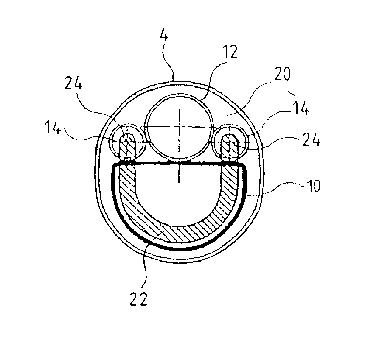
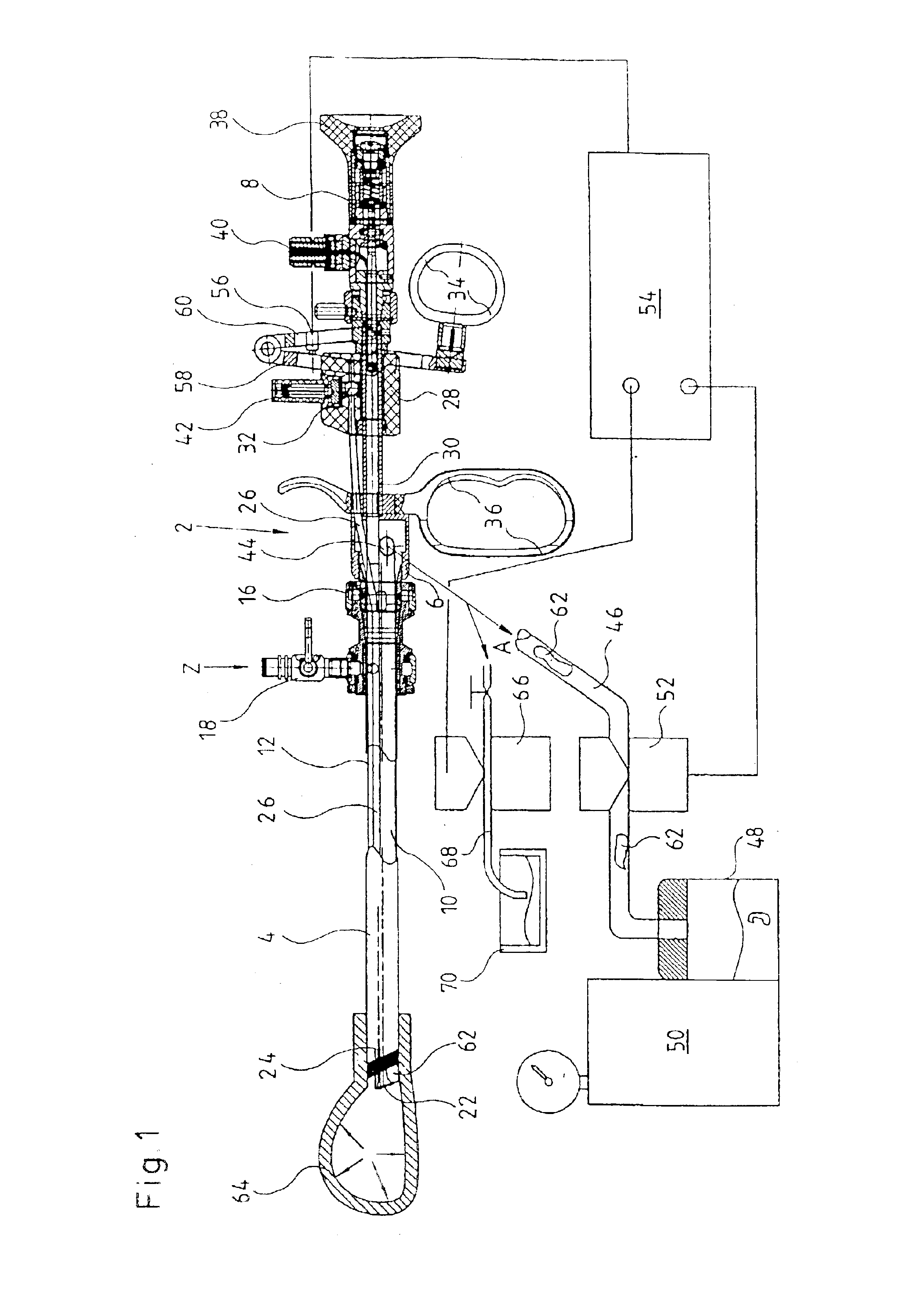
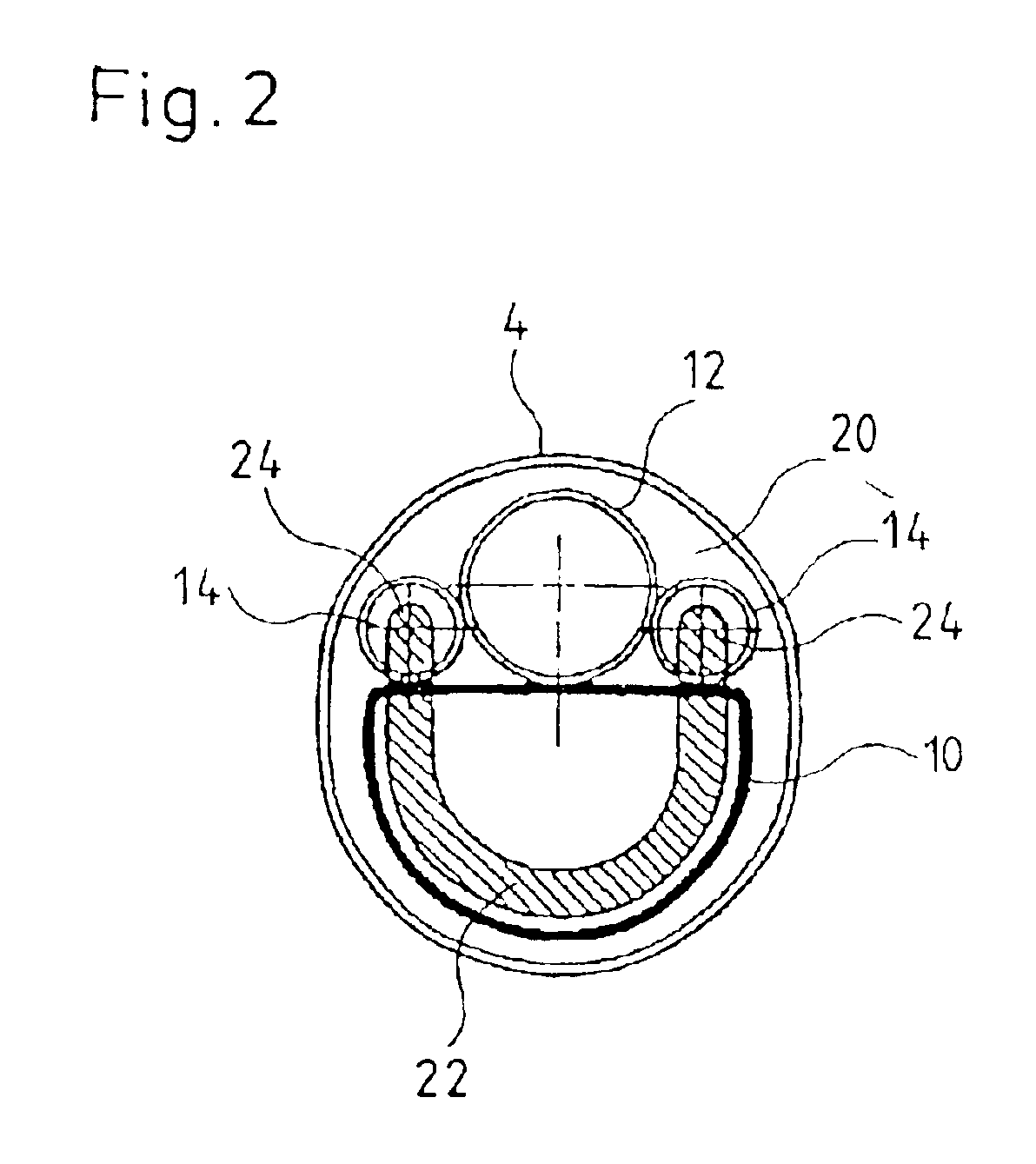
FIG. 1 shows a schematic entire view of the resectoscope according to the invention with the associated peripheral apparatus. The actual resectoscope 2 consists essentially of three parts, specifically a tubular outer shank 4, the working insert 6 as well as the optics 8. The working insert 6 is inserted into the shank from the proximal end of the shank 4. The working insert 6 comprises a suction channel 10 formed by a tube which is separate from the outer shank, an optics shank 12 as well as two electrode guide tubes 14 as is shown in the front end view of FIG. 2. The suction channel 10, the optics shank 12 as well as the electrode guide tubes 14 extend parallel to the longitudinal axis of the shank 4 through this up to the distal end of the shank 4. The working insert 6 is connected to the proximal end of the shank 4 via a known coupling cone connection 16. The shank 4 in the vicinity of its proximal end further comprises a blockable instrument cock 18 on which a supply conduit fo...


PUM


Abstract

In the inside of an outer shank there are formed a supply channel and a discharge channel which extend parallel to the outer shank. The suction channel has a larger cross section than the supply channel.

Description

1. Priority ClaimPriority is claimed for this invention and application, a corresponding application having been filed in Germany on Mar. 25, 2002, No. 102 13 200.3.2. Field of the InventionThe invention relates to a resectoscope.3. Description of the Related ArtWith known resectoscopes, after a certain number of individual cuts with which tissue parts have been detached, it is usual to lead away the detached parts together through the outer shank of the resectoscope. For this it is first necessary to remove the so-called working insert from the outer shank of the resectoscope in order to be able to make available a sufficiently large cross section for leading away or suctioning away the tissue parts. This manner of proceeding is relatively time-consuming and is thus a burden to the patient.From WO 98 / 43531 there is known a resectoscope whose cross section is divided into two parts by a separating wall, a larger part, which forms the suction channel, and a smaller part in which the ...

Claims


Application Information

Patent Timeline
Patent Type & Authority Patents(United States)
IPC IPC(8): A61B18/14A61B1/015
CPCA61B1/015A61B18/1485A61B2218/007A61B2018/00601
Inventor BOEBEL, MANFREDBONNET, LUDWIGBRUSTLE, SYBILLE
Owner RICHARD WOLF GMBH
Why Eureka
Try Eureka