Image formation device and agent supplying device including absorber conveying by negative pressure

a technology of image formation device and agent, which is applied in the direction of electrographic process apparatus, instruments, optics, etc., can solve the problems of high transportation cost, difficult cleaning for reuse, and the need to recover and recycle toner containers

Inactive Publication Date: 2004-11-30
RICOH KK
View PDF15 Cites 105 Cited by
  • Summary
  • Abstract
  • Description
  • Claims
  • Application Information

AI Technical Summary

Problems solved by technology

Recently, as environmental issues are increasingly valued, it is required to recover and recycle the toner containers.
The hard bottle toner container has many problems associated with its recovery and recycle possibility, however, because it elevates a transportation cost and is hard to clean for reuse.
The dried toner for electrography generally has a poor fluidity and a property to be aggregated easily.
Therefore, the use of the soft toner container to contain the dried toner for electrography makes it very difficult to discharge the toner from the soft container.
If such phenomena frequently occur, the toner in the tube may be compacted to cause the so-called "clogged" toner that can not be conveyed through the powder pump.
This problem can be easily caused in a single conduit type nozzle, in which a nozzle inserted into the toner container is communicated with an air path and a toner path, because the supplied air directly flows into the tube and pushes the toner therein.

Method used


Image

  • Image formation device and agent supplying device including absorber conveying by negative pressure
  • Image formation device and agent supplying device including absorber conveying by negative pressure
  • Image formation device and agent supplying device including absorber conveying by negative pressure

Examples


first embodiment

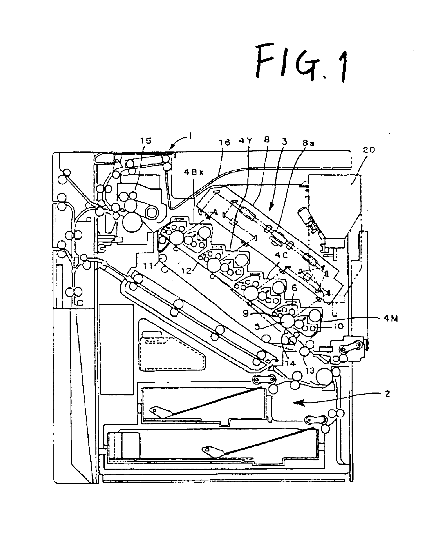
FIG. 1 shows an outline of a color laser printer, or an example of an image formation device, equipped with a toner supplement device as the agent supplying device according to the present invention.

The color laser printer includes a device body 1, beneath which a paper feeder 2 is located, and above which an image formation section 3 is located. The image formation section 3 includes a transfer belt device located in such a manner that it tilts downward at the paper feed side (the right side in FIG. 1) and upward at the paper discharge side (the left side in FIG. 1). The transfer belt device includes a plurality of rollers 11, and an endless transfer belt 12 suspended around four rollers 11 in this embodiment. For the sake of clarity, the reference numeral is given only to one of the rollers 11 in FIG. 1. When a driving source, not shown, rotates one of the rollers 11, the transfer belt 12 is driven to rotate counterclockwise in the FIG. 1. On locations opposite to the upper surfac...

third embodiment

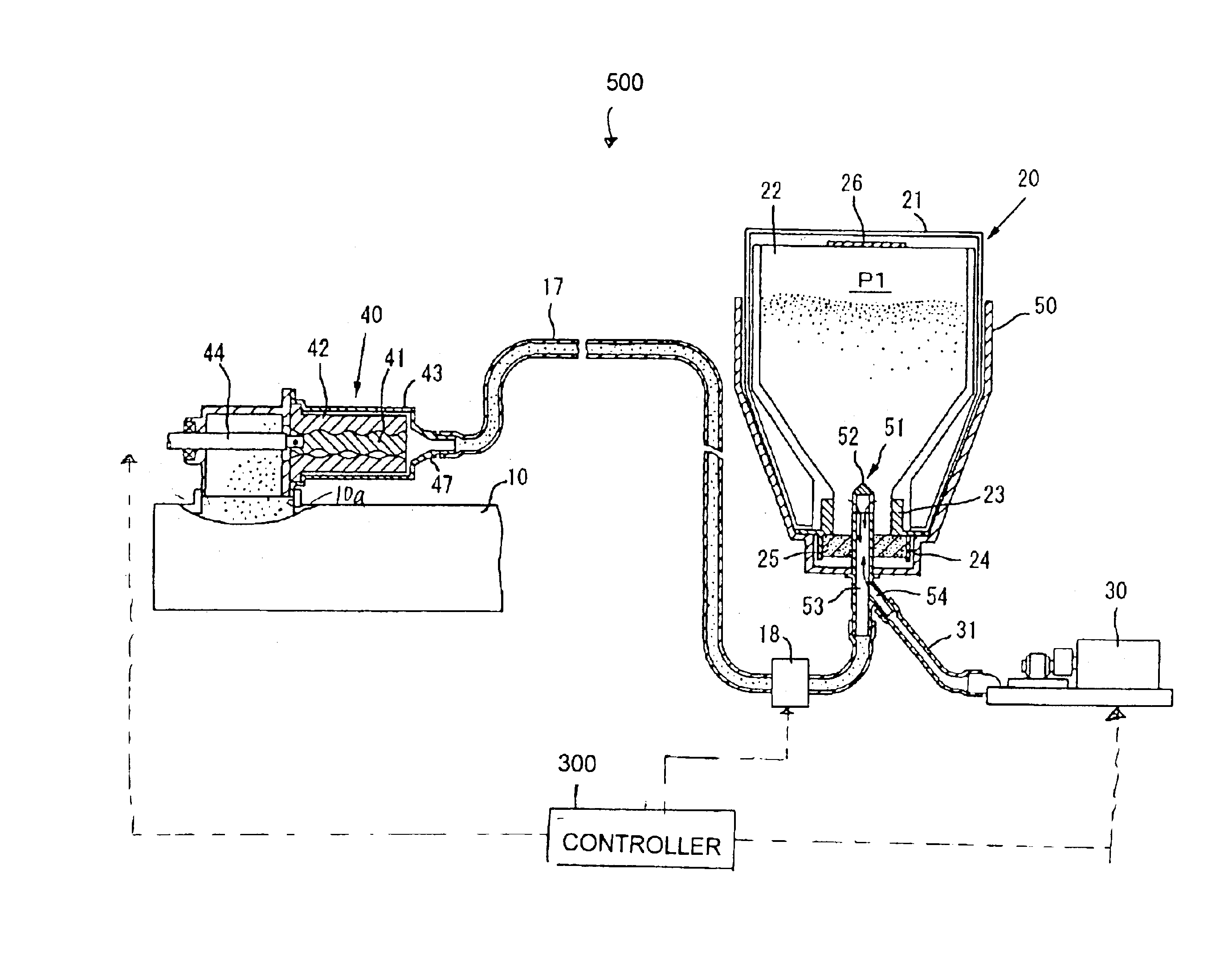
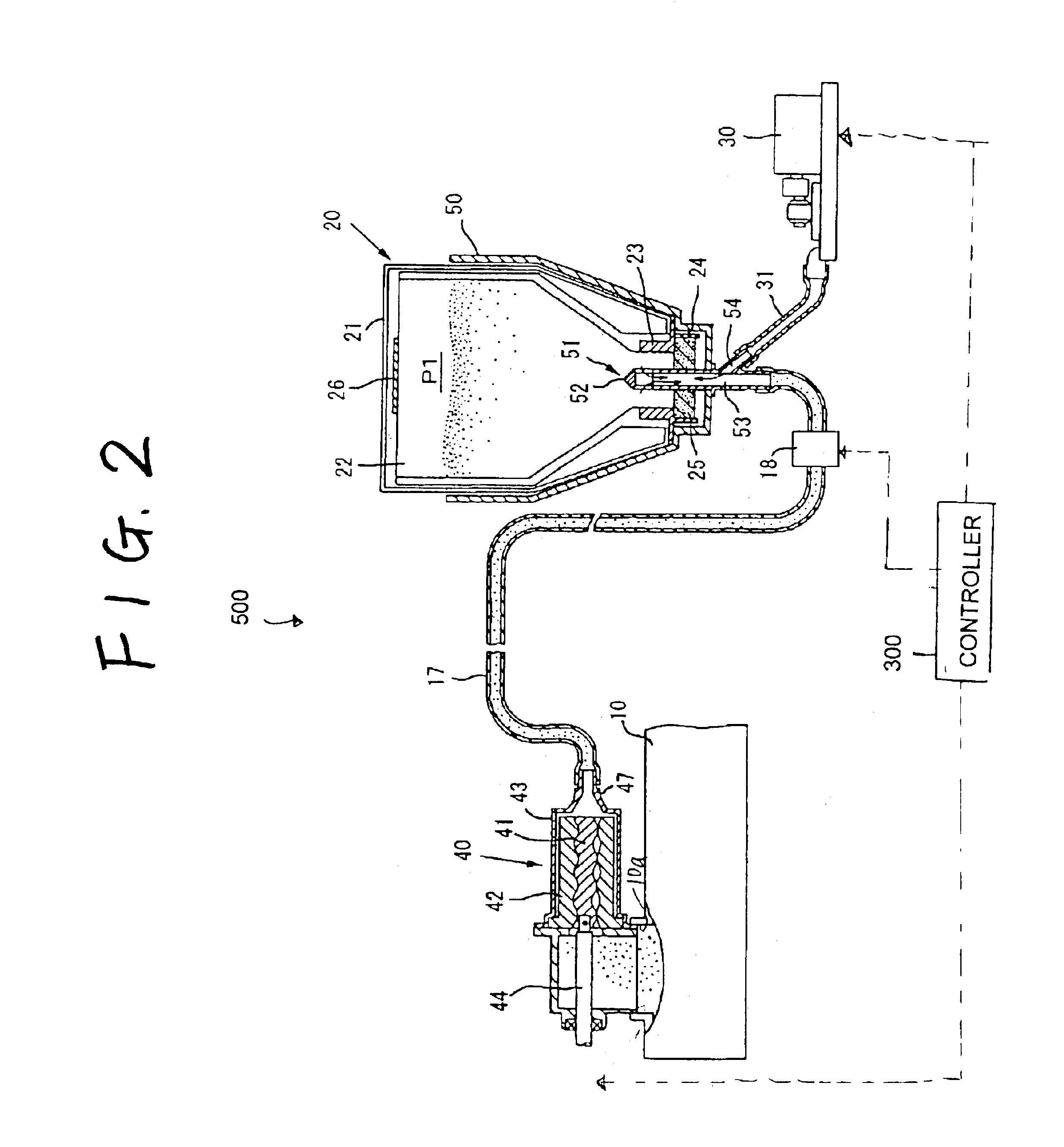
In the toner supplement device 700 of the third embodiment, the development device 10 includes a permeability detector 350 as a toner density detector. The permeability detector 350 detects a toner density in the development device 10 and generates a toner supplement signal if the detected toner density is below a predetermined density. When the toner supplement signal is generated, a micro-processing unit, later described, executes a control to turn on a clutch 46. As a result, the rotational driving force is transmitted from the driving source (not shown) of the image formation device to a driving rod 45 to operate the powder pump 40. When the powder pump 40 operates, the consequent absorbing negative pressure allows the toner contained in the toner container 20 to be supplied by a certain amount to the development device 10. The toner density detector is not limited to the permeability detector. For example, it may be one that detects a density reflected from the toner image on t...


PUM


Abstract

A toner container contains a powdery toner. A powder pump conveys the toner in the toner container to a substantially closed, certain location using negative pressure. A toner conveyance tube conveys the toner from the container to the powder pump. An air pump supplies air into the toner container. An on / off valve opens and closes the toner conveyance tube.

Description

1) Field of the InventionThe present invention relates to an agent supplying device that supplies agents, such as toner, a mixture of toner and carrier, and carrier alone, to a certain location from a container that contains the agents. The present invention also relates to an image formation device, for example, an electrographic printer, facsimile or copier.2) Description of the Related ArtA hard bottle type container is generally employed in the art as a container for use in an electrographic image formation device to contain dried agents, such as toner, carrier, and a mixture of toner and carrier (hereinafter referred to as "toner" generically). Such container may include an agitator inside serving as a unit that agitates and discharges toner. Alternatively, it may have a helical groove formed on the container wall for rotating the container to move and discharge internal toner. Another container includes no discharge mechanism and thus is required to supply toner manually.Recen...

Claims


Application Information

Patent Timeline
Patent Type & Authority Patents(United States)
IPC IPC(8): G03G15/08
CPCG03G15/0808G03G15/0877G03G15/0879G03G15/0886G03G15/0874G03G2215/0869
Inventor MURAMATSU, SATOSHIYOSHIZAWA, HIDEOKIMURA, HIDEKISUDO, KAZUHISAHATTORI, YOSHIOMATSUMOTO, JUNICHI
Owner RICOH KK
Why Eureka
Try Eureka